Wednesday 29 March 2017

Td5 D2 engine - Fitting the ProVent (2)

Finding a location to mount the ProVent into the Td5 Discovery engine bay was easy enough. Use was made of the space available on the bulkhead where an existing mounting bracket is already used by the fuel inertia cut-off switch.

The ProVent is shown mounted to the bulkhead next to the Turbo heat shield. The pipework has yet to be connected and will remain so while a suitable angled adapter is sourced for the lower drain pipe. This delay provides an opportunity to check how suitable the install is and if the fabricated bracket is up to the task of supporting the ProVent.


Another view of the install showing the 'piggy-back' arrangement with the fuel inertia cut-off switch on the bulkhead. The blue tape was used to catch any fixings that 'escape'  from the fixing process. A few days ago I managed to loose one of the original fixing screws in the engine bay so decided to take no chances.


A bracket was fabricated to 'piggy-back' onto this mount and once the arrangement was agreed, it was given a coat of Matt black paint. 

The squared enclosure has moved to a more central position. In addition, a piece of rubber matting was fabricated to fill the gap at the bulkhead mounting caused by the raised plastic lugs. The circular bracket shown above is supplied with the ProVent, everything else was fabricated.


Two views showing the bracket being assembled in place. A bit more fiddly to mount then I thought it would be, but perfectly do-able. I used some blue tape as a safety net to catch any nuts/washers that broke free.

I mentioned earlier that one of the original mounting screws was lost in the engine bay (somewhere down under the air filter box). I sourced some replacements using the other original screw as a guide...


Feel that I am asking a lot of these little screws to basically secure the ProVent to the bulkhead and I worry whether the extra bulk and weight will be a problem that may need solving with a completely new mounting?

Despite its size, the ProVent body is made from lightweight plastic (pa gf) and is rated to 120°C, but can withstand 140°c for short periods. That should be enough to withstand the ambient heat from the nearby exhaust.

Once the pipework is connected, the pipes themselves should provide a stiffer location for the ProVent.

Time to watch for the postie...


Wednesday 22 March 2017

Td5 D2 engine - MAP test (1)

Eager to use the Nanocom with it's on board SD Card to record diagnostic info whilst driving around.

Trying to 'read' and comprehend all the multiple data points of what the engine is doing whilst driving around is not to be recommended. In the past I have only used the Nanocom while stationary.

Since I have begun to study and adjust the engine management, I feel that having a printable record of all the existing data points before making any adjustments to them is advisable at the start so that any adjustments can easily be quantified and recorded for later comparisons. It may also be advisable to establish the same 'test route' to drive along when data logging...

Here goes nothing. 

23/03/17  -  Loaded a 8gb SD card into the Nanocom and connected to the OBD socket on Hx. The Nanocom SD function is not a 'hot' connection so it's important to insert the card (and retract it) while the unit is not powered up.

Once powered up the live data logging can be started by pressing the SD Card symbol. A text box opens up showing the files on the SD Card and prompting the user to select a file or create a new one. I plan to create a new file every time I do a test run, so I started by naming it  'T1'. 

Once created the file is opened automatically and a text message appears saying 'recording session started'. The Nanocom is now recording whatever set of data that was selected earlier.

Initially I selected the 'Inputs Fueling' data and was concerned that it would only record data that was on the actual screen I was viewing. There are four pages or 'screens' of fueling data on the Nanocom and it appears that every available parameter is recorded to the card.

It is possible to cycle through the available data screens whilst recording but I would hesitate to move to a different set of Inputs/ECU in case issues of the 'plug and play' nature crop up.

Have to admit it was a buzz to just drive away and know that all the data was being recorded.

I took Hx for a short run of stop-start traffic but also fast open road. I am still getting used to the improved response that the new MAF sensor has brought and was surprised how easily Hx now gets up to speed and is just a lot more driveable. Brought a smile to my face !

The data logging can be stopped at any time by pressing the SD card symbol and a text box appears saying 'data recording stopped /suspended'. I believe if started again it would resume writing to the same file?. 

I read online the it is important to switch off the unit fully before unplugging the OBD lead. This does not need to be done when no SD card is inserted. So once at the destination, I halted the recording then just closed down the Nanocom. There was no text box saying the data was saved or suchlike.

I did the same procedure on the return journey. When I selected the SD symbol I could see that the file 'T1' was on the card so I just created a new one 'T2' and drove on..

Back home it was time to see what was in the files. I connected to the laptop via the USB port. The Nanocom when fitted with a SD Card just behaves like an external card reader. It appeared to download some drivers to the laptop and then it was easy enough to locate the files and read them on the laptop.

The files straight out of the Nanocom are formatted in 'Word Excel' as a .csv file. Personally I don't have 'Word' but use 'Open Office ' instead. This program was able to open the files and offer some formatting as well.  I made copies of the files to the laptop to study and mess around with.

I read that the data range is written to the card roughly every second or so. A lot of info is generated. Even so, a lot can happen during one second. There is much info to be sifted through. Number crunching to say the least..

I had planned to upload it here but it just wouldn't be feasible.  After studying it, I should be able to extract comparable excerpts and present them here.

Sunday 19 March 2017

TD5 D2 engine - Wastegate Modulator (1)

Td5 Discoverys are fitted with a Turbocharger Wastegate Modulator controlled by the engine ECU.

It allows greater control (modulation) of the air pressure applied to the Wastegate Actuator mounted on the Turbocharger. In doing so it allows greater control over the generation and delivery of max- boost pressure which benefits the performance of the engine. 


The Modulator is bolted to the side of the engine block behind the water pump. Removing the turbo intake hose will allow easy access to the Modulator body. The four connections are as follows..

(1)  -  Hose connection to the air intake downstream of the MAF sensor. Used to evacuate or 'bleed' the applied turbo boost pressure that builds on the Wastegate Actuator. 

(2)  -  LOWER - Hose connection from the turbo outlet pipe. This supplies the turbo boost pressure used to control the Wastegate Actuator. 

(2)  -  UPPER - Hose connection to the Wastegate Actuator. This hose supplies the turbo boost pressure direct to the Wastegate Actuator. It is the pressure in this hose that is 'modulated' by the solenoid controlled internal valve of the Modulator.

(3)  -  Electrical connector (C0629) connects to the vehicle loom and engine ECU. Supplies live reference and control signals to the internal solenoid as required. The internal valve controls/modulates the connection between (1) and UPPER (2).

(4)  -  Locating bolts x2 (10mm)


Two views of fitted Modulators.

Td5 Defenders are not fitted with the boost modulator and rely on a direct small-bore hose connection from the turbo outlet hose direct to the Wastegate Actuator.

Routing the pipework 'direct' on a Discovery and in effect by-passing the modulator is a workable option, but it will allow 'Wastegate Creep' to develop and compromise delivery of the available boost pressure.


MODULATOR PERFORMANCE  - 

Road Testing

Driving on an 'open' road going uphill will put the engine under max load. The Modulator is designed to assist the engine performance by allowing the turbo to maintain its maximum safe boost level for longer.

Beyond a certain engine rev/boost level (c.2500rpm), the ECU begins to send a variable modulated signal to the Modulator that controls the opening and closing of the internal solenoid valve. 

This has a direct effect on the developing Turbo boost pressure which will begin to stabilise in order to prevent the engine over-boosting. 

If the modulator valve does not operate and stays closed, the turbo boost pressure will continue to build and operate the Wastegate actuator directly. 

Depending on the setting of the Wastegate actuator, this condition will mirror the Defender Td5 set-up and could lead to Wastegate Creep. If the modulator valve fails to close completely when requested then the turbo boost pressure inside the modulator will leak away and potentially full boost or indeed 'overboost' will be achieved before the wastegate valve opens. 

If the engine develops enough Turbo Boost to achieve a dangerous overboost condition, this will be detected by the engine ECU/sensors and trigger a cut-back on the fuelling of the engine. This is a safety measure and it will be felt by the driver as 'hesitation' and the power will seem to cut-off and then return and repeat at the same engine rev. range. LR designed this as a safety feature to protect the engine and its occurrence should NOT be ignored.


MODULATOR PERFORMANCE  -  

Using a 'Nanocom' diagnostic reader

The Nanocom offers a system check that will operate the solenoid when the engine is stationary. The operation of the modulator can be determined by listening for the 'click' of the solenoid.

There is also a number of read-outs on the Nanocom that can be used with the engine running to determine the performance of the modulator.

'DIAGNOSTIC CAPABILITIES  -  SETTINGS' Wastegate Modulator (%) measures the 'duty ratio' of the Modulator as a %. The readings range from 0% to 40% and indicate how long in a given period that the solenoid is active and thereby modulating the Actuator pressure supply.

The Nanocom has a one second sample rate, whereby the Td5 ECU can sample data many hundreds of times per second. 

'DIAGNOSTIC CAPABILITIES  - INPUTS' 
 Wastegate Modulator - as above but shown next to 'manifold turbo pressure'

'INSTRUMENT MODE' - screen 5 - wastegate % Also - screen 1 - engine speed - Turbo pressure

I need to connect the Nanocom to Hx and record these values while driving around to get a better idea of how the engine is currently operating. 

I recently cleaned/replaced the MAP and MAF sensors which each brought big improvements and I have confirmed that the Wastegate Actuator and valve are physically free to move.


REPAIR / REPLACE.

There are no user-serviceable parts inside the Modulator and replacement is the only real option....

The Modulator Solenoid is readily available and it's replacement is an easy task. 

I have read many online comments that speak of the benefits of replacing the unit, but most seem to be related to issues of hesitation or lack of boost which could well be symptoms of a faulty Modulator. Bear in mind that the unit operates by modulation of the control signal meaning it can be cycled open/close very rapidly. After many years use it could well be getting tired, leaking pressure, or sticking.

In the case of Hx, I have noticed how oily deposits from the turbo outlet have been ingested by the modulator, and passed through the wastegate actuator and then deposited into the turbo intake hose. While this could well provide a degree of lubrication, it could also interfere with the internal electrical contacts...


Further reading.

DiscoTd5.com   -  In-depth explanation of the workings of the Modulator.

Discovery2.co.uk  - Good description of the Modulator and its replacement 


Td5 D2 engine - Fitting the ProVent (1)

In the Td5 Discovery engine bay, there is a handy space on the passenger bulkhead (UK model) to mount the ProVent unit.

Some models mount the Fuel Burning Heater there, but Hx just has the inertia switch for the fuel cut-off mounted on to an accessible bracket welded to the bulkhead. There is a soundproofing blanket over the bulkhead that hides any other potential mount points and I am presently reluctant to remove it.

I intend to piggy-back the ProVent to the inertia switch mounting by fabricating a metal bracket that will attach to the switch mount and hopefully provide enough support free from vibration and strain for the ProVent.

Started searching around for suitable bracket material and was lucky to find a discarded boiler mount-plate that was a perfect source...


The angle plate needed to be cut out, but the angled brackets were a lucky find. 

With the ProVent mount ring in place. Nothing is attached yet and some bolt-holes need to be drilled/enlarged once the final position is agreed. The existing Fuel Cut-Off switch will be in the square enclosure. 

It will be possible to move the 'square' bracket to a more central position if required.

Positioning the bracket as above will provide enough clearance to the nearby turbocharger heat-shield, but shifting the bracket to a more central position will achieve better balance yet still allow the necessary physical clearances around the unit.


This is the fuel cut-off switch mounted on the bulkhead. The turbo is to the left and the shadows seen are from the ABS pipes. There is ample space here for the ProVent to be mounted and to route the pipework.

The fixings for the switch are two small screws that locate in white plastic plugs. I can only hope that they will be adequate to support the added weight of the ProVent unit. 

Update. ... just managed to loose one of the screws inside the engine bay..!!

Friday 17 March 2017

Td5 D2 engine - ProVent, a better breather

Have been thinking about how to improve the engine breathing to ensure that only clean cooled air enters the intake manifold.


All running engines internally produce 'blow-by' gases that need to be vented safely otherwise the build up of pressure inside the running engine will only lead to blown gaskets and broken parts. 

These 'blow-by' gasses are mostly hot oil-mist particles suspended in air.

Most engines achieve this by installing an outlet on the rocker cover that directs the blow-by gasses back into the intake system. It relies on the intake depression to help evacuate these gasses, but some systems simply vent the gasses to the atmosphere and rely on the 'blow-by' pressure to evacuate them.

Putting dirty, oily air into the engine intake stream may well satisfy environmental concerns but it is not good for the engine 'breathing' and just leads to the oil-vapour particles condensing, collecting and coating the inside of the air intake manifold, the hoses and the Intercooler.

In extreme cases this can lead to the 'Runaway Diesel' syndrome, where the engine will continue to run on these vapours alone.

Manufacturers are aware of this and design a crankcase venting system that incorporates some kind of filtration designed to catch the oily vapour and in theory allow only cleaned air to pass into the intake stream.

The Td5 apparently has specially designed 'swirl-chambers' built into the rocker cover that are designed to remove excess oil from the oil-mist before it leaves the rocker cover. As Rave puts it...

... " The rocker cover features circular chambers which promote swirl in the oil mist emanating from the cylinder head and camshaft carrier. As the mist passes through the series of chambers between the rocker cover and oil separator plate, oil particles are thrown against the separator walls where they condense and fall back into the cylinder head via two air inlet holes located at each end of the rocker cover" ...

All that happens inside the rocker cover and it is maintenance free for life. Unfortunately, despite the good intentions, oil particles are still carried out of the rocker cover to be deposited into the intake stream and given time, the oily gunk will coat the insides of the intake manifold and the Intercooler leading to reductions in their thermal properties. 

Once the blow-by gasses leave the rocker cover they are directed into the intake airstream via a one way Depression Control Valve (DCV) mounted downstream of the MAF sensor but upstream of the turbo.

It is highlighted in the above image and the trailing hose leads back to the rocker cover.

Reckon some people mistake this unit for being an oil separator. All that it does is regulate the flow of the oil bearing gasses into the intake stream. 

When the turbo spools up and the suction pressure increases, the turbo will draw heavily on the rocker cover gasses and if unchecked could suck out all the oil! This 'depression' valve responds to the increased vacuum draw and closes off the outlet to the Turbo intake till the pressure returns to a set level. In doing so, the unit is able to maintain 'positive crankcase venting' at an acceptable level.

I wonder if there is a way (other then sucking on it) to check the operation of this valve or to find out at what pressure it operates? 

Perhaps its safer to just replace it with a new unit. There is no maintenance procedure for it other then replacement. The unit can fail in use with little visible warning. The ProVent unit I intend to fit has its own version of this valve so I have the option of removing this LR part..

At the very least I intend to remove it from Hx and give it a good clean through with meths. I have already removed it once and the pipework that it attaches to when working on the MAF sensor and discovered a trail of oily deposits inside the intake pipe obviously emanating from the valve outlet. 

More alarmingly, I took this photo of an oily deposit in front of the turbo inlet.


I can see that after fitting the ProVent and getting it up and running, I will have to clean all the components  downstream of the Turbo including the Intercooler and the intake manifold.....

Hopefully the installed ProVent will in future clean up the oily mist coming from the rocker cover before it enters the intake stream. The easiest method is to just vent the pipe to the atmosphere. But that does away with the 'positive venting' that the intake air-stream encourages and is not recommended.

The unit I decided to fit is a 'ProVent 200' made by 'Mann Hummel'....


They are not cheap and they never have been. Also, they are not readily available and my research only produced a couple of suppliers who seem to even know it exists.

I ended up getting one from an Industrial Filtration specialist 'MFE' based in the UK.

It is a lot bigger then it looks! It's instillation is a custom fit and a suitable location in the engine bay must be found. Luckily the Td5 Discovery has enough space on the bulkhead alongside the turbo. (Assuming the 'fuel burn heater' is not fitted!). Hx has its fuel cut-off solenoid mounted here on a convenient and accessible bracket welded to the bulkhead and I decided to fabricate a mounting for the Provent that will 'piggy-back' onto it.

The other concern is that the Td5 pipework is 19mm ID where the main inlet and outlet on the ProVent is 25mm. Reducers can be bought to accommodate this.

I ended up needing the following for the plumbing :-
  -  1 metre of 19mm ID clear reinforced hose
  -  500 mm of 13mm clear reinforced hose
  -  Two 25 to 19mm reducers 
  -  Two 19mm straight plastic connectors 
  -  One 19mm 90° bend connector 
  -  Hose clips x8

I opted to get clear hose just so any deposits can be seen inside them. The 13mm hose is for the 'oil drain outlet' on the base of the unit.

I tried to get this stuff in the local DIY stores, but it was just a waste of time and effort. The Internet won again..


See Also  - "Td5 D2 engine - Fitting the ProVent (1 - 4)"  for a description of fitting the ProVent 200 to a Td5 engine...


Tuesday 14 March 2017

Td5 D2 engine - Turbo Wastegate (1)


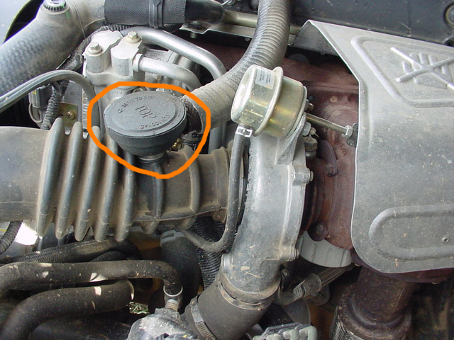
The turbocharger on a Td5 engine is a Garrett design that comes complete with a Wastegate Actuator mounted onto the turbo body. The wastegate actuator is highlighted in red below...

The adjustable control rod extends under boost pressure to move a pivoting shaft that opens a small valve internally in the exhaust side of the turbo.

The above photo shows a generic Wastegate Valve fitted inside a turbo-charger. The control rod can be seen attached to the outside of the valve stem. The wastegate valve opens internally into the exhaust side of the turbo body and allows the exhaust stream to by-pass or 'bleed' away from the spinning turbine thus reducing the generated 'boost' pressure in the inlet manifold.

The function of the wastegate-valve is crucial to stop the turbo over-boosting the engine and things quickly going BOOM.


OPERATION AND INSTALLATION


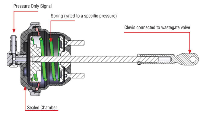
The body of the Wastegate Actuator is bolted to the body of the turbocharger and it contains a strong spring and diaphragm that normally hold the wastegate valve in a closed position. 

When sufficient air pressure is applied to the actuator, the spring will compress and extend the control rod which in turn opens the wastegate valve. The pressure is supplied via a small-bore hose connected to the Intercooler intake. The available pressure is itself generated by the spinning turbine.

There is not much in Rave about the operation or installation of the Wastegate on the Td5 Discovery other then it's connection to the 'Wastegate Modulator'. (see below).  


PROBLEMS WITH THE WASTEGATE.

The turbocharger produces maximum boost at around 3000rpm. If the engine is driven gently and economically it will seldom get to 3K rpm!!.  Long periods of non use won't help either. If the wastegate mechanism is seldom operated, the physical valve inside the turbo can seize due to the intense heat and the deposits from the exhaust stream,

I tried to move the wastegate operating arm manually using a wrench clamped onto the shaft. Nothing would move either back or forth. I had watched some YouTube vids to get an idea of what to expect, but the lack of any movement was a worry and I had to investigate more. 

It's also possible that the Wastegate Actuator can develop an internal leak from a worn or punctured internal diaphragm.


REMOVING THE WASTEGATE ACTUATOR.

The two 10mm nuts holding the actuator body to the turbo body are easily accessible. The clevis-pin connecting the arm to the wastegate valve is nicely hidden under the heat shield. It is possible to spray the valve shaft housing with lube to help free it up, but better access will be gained by removing the heat shield.

There are three bolts that hold the heat shield onto the exhaust manifold. Two have easy access, but the third one is hidden and fiddly to get at. It is screwed into the hottest part of the exhaust manifold and will almost certainly be seized and ready to snap off. 

As expected, the third bolt was very tight and I was weary of shearing the head. That would allow the heat shield to just rattle away and it could even fall down onto the turbo body. I decided to drill out the rivets holding the heat-shield upper panels together and to bend the upper panel to allow access to the control rod. It was easy enough to re-secure the panels with two small nuts and bolts.

Once removed it was much easier to physically move the rod against the pressure of the internal spring. 


I am assuming that the fitted actuator has the same 'spec' for all Td5 engines? I find myself wondering what the internal springs natural tension is as opposed to the 'applied' tension from the control rod adjustment?  I'm thinking that springs of differing 'strengths' will react faster/slower to the same applied pressure?... That would in turn effect the reaction time and the physical movement on the wastegate valve spindle..   Hmm, more research needed!!


WASTEGATE SPINDLE.

Attention then turned to the wastegate valve operating spindle mounted on the turbo body. 

Here is a photo from the Web that shows a typical Wastegate Valve mounted onto the exhaust side of the Turbocharger...


The spigot above the thumb is where the Actuator control rod attaches.

Liberal spraying of WD and some pliers soon had the lever shaft moving freely. I found that it will only move back and forth about 1/3 of a turn..

I read somewhere that lubricating the shaft is not recommended due to the harsh operating temperatures and the risk of the lube gumming-up in there.  


The linear movement of the control rod is limited by 
the spring compression in the actuator body. It seems all the 'action' takes place via this controlled little movement. At rest, the control rod must hold the spindle closed, otherwise the pressure building exhaust stream will be bled away from the turbine via the open valve which can only decrease the available generated boost.


BENCH TESTING THE ACTUATOR.


The control rod is fitted with a lock-nut and a black knurled rotary adjuster to alter its length and adjust the available boost. This is a factory set adjustment and there is no mention in Rave about altering it in service. 

Altering the length of the control rod has a direct effect on the available boost pressure. Turning the adjuster just one turn can bring benefits or indeed downfalls!!. Caution is advised, but it is now a possibility.

Manually extending the control rod against the pull of the spring is physically demanding and I got to wonder just how much pressure is needed to operate it? Even at this stage I was unsure whether the unit was vacuum or pressure fed. 


I placed a bicycle stirrup pump onto the hose connection and used some blue tape as a visual marker. The pump is fitted with a wide reading gauge but it's accuracy is untested.

   
      ...this is at rest or zero psi...

..and this is maximum extension at 20 psi.

The control rod started to lift around 10psi and extended smoothly. I kept the pressure on for a while to check the unit was airtight.

When fitting the Actuator back onto the turbo, I used the pump to easily align the control rod end with the wastegate valve shaft, making easy work attaching that fiddly clevis-pin.


So I am now confident that the Wastegate Actuator and the valve in the turbo are working together as they should. I still need to check the solenoid modulator and it's pipework.


ADJUSTING THE BOOST. 


Just for the record, when I dismantled the adjuster I was careful to record the locknut position by carefully counting the screw threads visible.


I made the above notes after reading that even half a turn can make a difference. I went ahead and shortened the rod to show 12 threads before re-mounting it on the turbo body. In theory it should increase the boost. 

I now have to connect the Nanocom and study the boost readings closely to assess the situation..... (Update...This 'situation' is still ongoing and is detailed more in other blogs).


THE WASTEGATE MODULATOR.

Tracing the path of the small-bore rubber hose attached to the Wastegate Actuator will lead to the Wastegate Modulator. The body of the modulator is bolted to the side of the engine block.


Td5 Defenders are not fitted with the modulator and their Wastegate Actuator is plumbed directly into the Turbo outlet via the small-bore hose. Both versions use the generated boost pressure to open the Wastegate Valve once the boost pressure builds and overcomes the resistance of the Actuator spring.

A Td5 Discovery engine will get 'on boost' quicker and for longer then a Td5 Defender. Eliminating 'wastegate creep' is one reason for fitting the solenoid controlled valve onto the engine. There is a performance gain to be had this way.

See also: Td5 D2 engine - Wastegate Modulator 


Td5 D2 engine - MAF Sensor (3)

The new MAF sensor arrived today from JGS4X4. I have bought from them before and when you consider that I ordered it on Friday and it arrived the following Monday morning, that's a good service..

There is a lot of discussion out there about only buying the official LR OEM sensor. All the others are deemed to be cheap nasty copies that give 'false readings' in use. It's difficult to qualify statements like that without testing a whole range of these sensors. It's easier to accept that expense equals quality.

A new 'Siemens' branded unit is north of £80. Other unbranded or 'aftermarket' units can be had from £15 upwards. There is even a busy second-hand market in these things, - plenty of ways to be landed with a turkey!

So it comes down to cash flow. Even the parts suppliers must consider this when deciding which manufacturer/distributor to get their stock from. I also like to think reputable suppliers will have one eye on their own reputation for selling quality parts...

When looking around for the replacement sensor, I priced the local independent LR garage who stocked Britpart for £35 .  JGS4X4 where cheaper by £8 , but didn't state what 'make' it was. (listed as unbranded). I took the gamble figuring I could then buy a new stock air filter with the difference.

That whole 'Britpart' question turned up again. I got to thinking that as they seem to offer a 2 - year guarantee on everything these days (no doubt because of the bad rep) they should be back up there. So I was kind of wanting the new MAF to be a Britpart..

This is what I ended up with. A cheap and cheerful pattern copy. At least the 'stock' date is recent. There is no branding or any markings at all on the sensor body except for the airflow direction arrows. 

Studying the unit closely gave me the impression that it was maybe even a refurbished unit. There were more clues as to the way the sensor unit is mounted in the tubular body. Excess bits of a black rubbery mastic type glue were to be seen.

But by far the biggest difference was with the sensor wires. I was expecting the same arrangement with two fragile wires but instead this sensor has two resistors soldered in place. 

It is possible to read off the colour bands on the larger resistor. I have no idea how this set up will compare to the original one. I can only hope it gives 'correct ' readings..

Another image of the new sensor. Of interest here is the small hole visible on the mirrored base-plate of the sensor. Whats that about I wonder? Also, that mirrored surface is not as smooth as the original and has what looks like fingerprints on its surface!!

So, all things considered, I tried the resistance tests across the pin out terminals..

NEW MAF RESISTANCES 

PIN 1-2  =  194K OHM
PIN 1-3  =  1670M OHM
PIN 2-3  =  1960M OHM

At least I got a reading even though they are nothing like I was expecting. Think I'm in un-chartered territory here..

15/03/17 - Went ahead today and fitted the new MAF filter to Hx. Went out on a test run. Right from the start it was possible to feel that the engine was more lively and willing. 

Took the Nanocom along and plugged in to the OBD. At idle, the 'instruments' diagnostic gave the following..

IDLE  SPEED  -  744RPM
COOLANT  -  59.5°C
TURBO PRESSURE  -  0.04
AMBI PRESSURE  -  102.37

AIR FLOW  -  64.5 G/HR

AIR INLET TEMP  -  25.3°C
FUEL TEMP  -  53°C

The new MAF filter now measures the correct airflow value at idle. It should be in the range of 55 - 65 g/hr. Glad to see its right up there.!

Air flow at 2k rpm is now 343g/hr. The old filter was showing 200g/hr.

I continued to drive around with the Nanocom connected, but I gave up looking at the numbers in favour of enjoying the drive! 

The Nanocom offers the facility of recording data to a SD card so that it can be studied later rather then driving with one eye on it trying to remember the values!!  - a lot safer.

So, to conclude, replacing the original MAF sensor with a cheap and cheerful copy has brought the engine back alive. 

Let's see how long that lasts.


Monday 13 March 2017

Td5 D2 engine - MAF Sensor (2)

With a new MAF on its way, I decided to delve more into the construction and workings of the MAF sensor using the removed example.

I started to think about removing the actual sensor from the MAF body. This will no doubt end in the destruction of the unit but I am so curious as to how it is assembled. Just as curious to discover the meaning of the mirrored surface on the sensor base.

Read that in operation, one of the wires can get heated to +200°C above the ambient temp, so there is probably some strong insulation going on here... The sensor wires are supplied with 12v so in theory I guess (without seeing inside) the wire itself gets 12v and therefore is going to have to be pretty thin to achieve the resistance value to get to 200°C. Add together all the duty cycles running hot and cold, the thermal expansion pressure and the engine/suspension vibration... Tough time in a harsh environment.  Respect the MAF  !!

Attention turned to the two wire elements. The resistance readings I obtained would suggest that their circuit was broken. I probed the mountings of each wire for continuity and there was none. Perhaps these wires were already snapped.?

The wires are very fragile and their delicate mounting seem flimsy. I guess this is to do with their resistance properties. I'm beginning to see why they are so expensive. The manufacturing tolerances must be high and that in turn raises the quality control, the expected lifespan and the end cost.

All of the blogs that talk of cleaning the MAF clearly state how delicate the two sensor wires are and to avoid any contact with them. In theory, any 'dirt' particles can only come downstream from the air filter carried on the air stream and to settle on the tiny heated wires is a big ask. I guess the big concern would be residues burnt onto the surface of the wires altering the thermal cooling of the wires and thereby leading to 'altered ' readings.

I started to think that the wires themselves through their heating action are probably self cleaning and should be left alone if there is no visible debris on them.

The cleaning method is to use aerosol contact cleaner, carb cleaner or even WD40.  Even the force of the spray can sometimes break the wire. Evaporating cleaners work best. They need to dissolve any dirt then wash it away and evaporate. I decided to use Meths and some electrical switch cleaner. .

Initially I thought of making a 'bath' of meths that I could sink the whole sensor into (at least up to the wires), but on reflection abandoned that idea. The only visible dirt I could see was on the end guards and caught on the fine wire mesh behind the 'leading' guard. Photos were taken before the cleaning began..


I resorted to pricking out the dirt from the wire mesh using a thin wire poked through to dislodge it. The internal surfaces of the sensor were wiped down with a cotton bud soaked in meths. There was not much dirt in there at all. I wiped the sensor mount carefully and avoided the actual wires. There was a little yellow spot on the sensor mount body that dissolved away with the meths.. I assumed it to be some kind of manufactured colour code?

At this point I had a clean but none functioning sensor. Attention now turned to the wires themselves.
It was impossible to see any breaks in the wires so I decided to physically touch them with a probe and sure enough the first wire tested flexed away from one of its mounts confirming a break and the lack of continuity and the infinite resistance. The second wire, well see below...


This wire just disintegrated before I could visually see any separation from the terminals. Luckily I had placed a piece of plain white paper inside the sensor to act as a non-distracting background. The paper caught the wire fragments and revealed the golden colour of the 'wire'.  This made me wonder if the wires are actually gold, considering the electrical non-tarnishing qualities of the metal. ?

Alas, not gold! I mean if studied real close it is possible to see that the 'gold' colouring is indeed some kind of non-conducting coating on the surface of an exceptionally fine wire. 

Research on Rave and on the net speak of a 'film coated wire' at the heart of the sensor. 

I then set out to get continuity between the wire mounts by using bare wire and test leads...

I was quickly able to confirm continuity between all the sensor-wire 'poles', but I could not get any continuity to any of the 3 pins on the connector. I was getting ready to break-in to the sensor body when the postman brought me this. ...


.. the new MAF sensor.