Sometime last year, a small LED strip was attached to the rear of the centre console below the fitted ash tray. The intention being to have a rear foot-well courtesy light that would compliment the rear passenger door 'marker' lights installed earlier on the modified rear door speaker grills.
The LED strip is wired into the front foot-well lighting circuit with the supply wiring routed under the centre console and hidden from view.
Once a suitable position was found, the LED strip was attached to the lower rear console surface with two small strips of Gaffer tape. Needless to say, this temporary install quickly became semi-permanent and the only attention needed was to renew the little Gaffer strips whenever they became un-stuck. It was always my intention to mount the LED strip in a more permanent way to the console in order to make it look more factory-fitted.
Research showed that the rear of the console will actually detach from the console body. It is held on by four small screws which are easily accessible despite being tucked away, two on each side between the console and the front seats. I decided to remove the rear console lower cover and install the LED strip permanently by cutting a narrow slot to mount the LED strip behind.
Furthermore, looking at the seldom used ash tray gave me the idea for a better use of it's mounting place..

Furthermore, looking at the seldom used ash tray gave me the idea for a better use of it's mounting place..

Ash-tray unit about to be re-purposed.

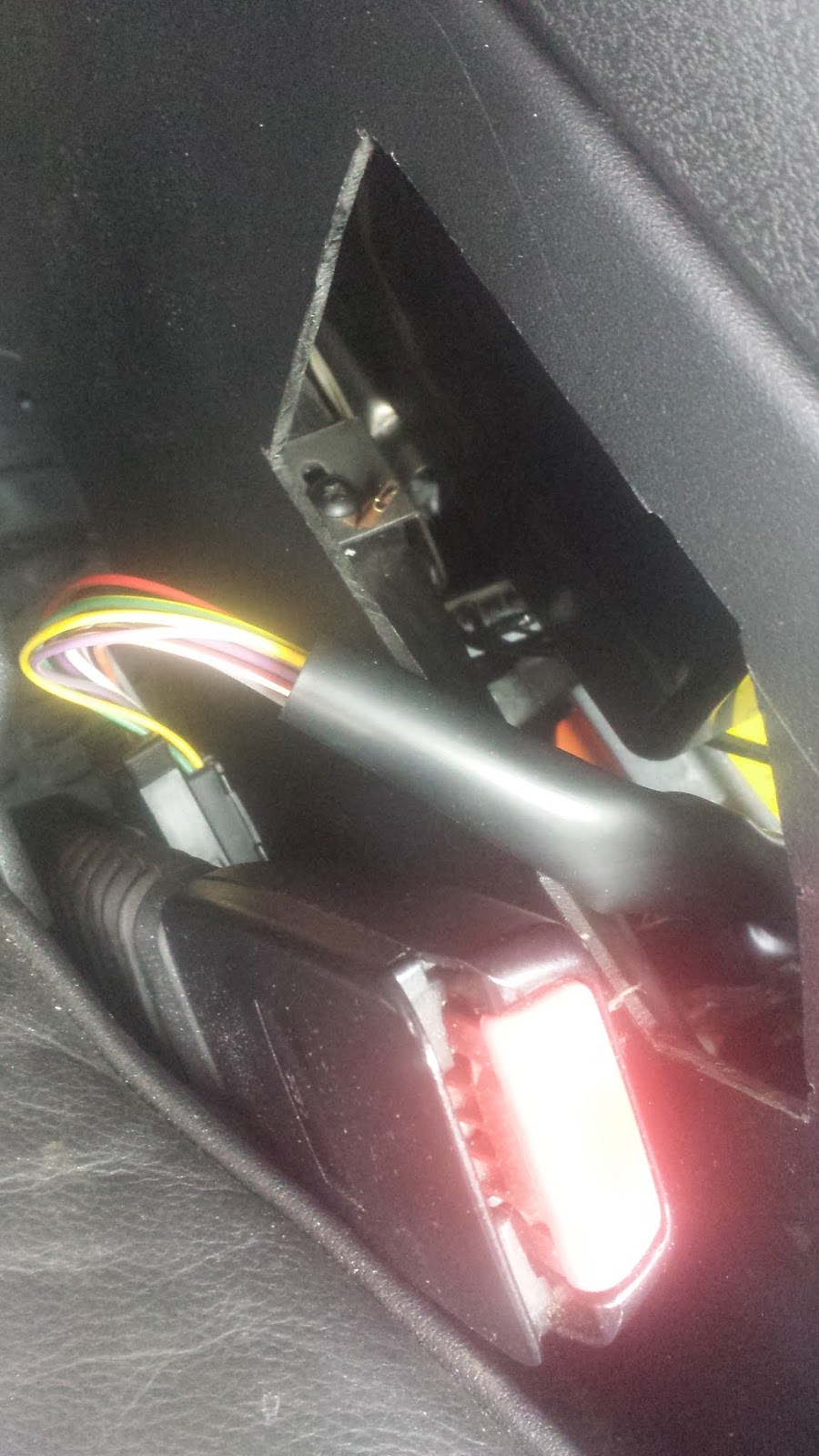
The image above shows the removed console on the bench as if looking up from the floorpan of the bodyshell.
The two cut-outs with rounded corners are for the heater/air-vents into the rear footwells. The narrow slot is the newly cut aperture for the LED strip. The ash-tray mount can readily be seen and the whole ash-tray assembly is a simple push/snap-fit into the console body. Removing the ash-tray unit from the fitted console will give easy access to install any additional wiring inside the console.
Having placed the LED strip and decided it's final position, I wanted to have the install look more factory-fitted then just simply 'stuck-on'! At this point, I even thought about mounting a switched acrylic-lens light unit not unlike the factory fitted front courtesy lamp (size wise, the glove-box light unit would be more suitable). I decided against this as I couldn't see a need for the foot-well light to be manually switchable and besides the thin-strip format of the LED would look much more contemporary, stylish and 'hidden'.
Measurements were made and positions marked out. It was a simple enough task to cut out the narrow strip to mount the LED behind. I used a combination of a sharp craft knife and a small cutting wheel mounted on a Dremmel type tool. A strip of good old Gaffer secures the strip onto the inside of the console.

This image shows the LED light strip in its fitted position. Should the LED ever develop a fault, all wires and connections will be accessible when fitted by removing the console. At this point, I still have the option of fabricating a clear acrylic strip to mount flush to the outer surface for a 'factory-fitted' look...
ASH-TRAY PANEL MOD.
Decided to remove the ash-tray and replace it with a panel mounted 12v Aux socket with a double USB socket alongside. E-bay was consulted and pretty soon this arrived direct from China for pennies..


They each have rubber covers and the USB socket has a miniature blue LED 'power-on' indicator..
The above unit was supplied with screws and spade terminals to connect everything up. The sockets can be detached from the supplied mounting plate which will allow for more mounting options.
Mounting Panel - Front.
I decided to make a custom mount panel that can be fixed in the space created by removing the ash-tray unit. I found a suitable piece of soft panel wood and devised a mounting method using the locking rings from the two sockets to secure a custom made bracket that will clamp the panel to the inside of the rear console.
The wooden panel was marked out and I began making the holes needed for the socket bodies..


Pilot holes where carefully drilled through the wood and a craft knife was used to cut-out the hole. A half-round Bastard file was then used to clean-up and shape the hole..

With two new holes in place, the panel was finally cut out using the craft knife and filed back to fit into the console..


Here's a view of the fitted sockets on the mounted panel. I intend to stain the wooden panel with some wood-stain that should hopefully match the rest of the 'wooden' panel trims. Failing that, a quick spray of Satin Black should do the trick.
Mounting Panel - Rear Bracket.
Needed to make a rear mounting bracket to secure the wooden panel to the console. I planned to make use of the existing moulded ridge on the rear of the console that locates the ash-tray unit and to use the locking rings from the sockets to secure it all in place..

A paper template was used to get some idea of the shape/dimension required for the bracket

Decided to use thin metal plate for the bracket and some suitable Aluminium plate was sourced. I used a redundant printing plate that was easy to 'work' using simple hand tools..

The 90deg bends were formed by hand using a vice. All the holes were drilled by hand using the craft file shown above. It was easy then to enlarge the holes in order to remove the central disk...

A final tidy up was done with a half-round Bastard file just to remove all the sharp edges.

The fitted metal bracket in position on the back of the console. It can be seen how the 90deg bend wraps around the moulded ridges on the console.
When fitted it was observed that there was a small gap of a couple of mm between the rear face of the front mounting panel and the rear securing panel..

The gap is easily closed up when securing the sockets with their locking rings, but it's just as easy to fill the gap with a filler plate made from corrugated cardboard..

12v SUPPLY, FUSES AND CIRCUITS.
LIGHTING - The LED strip already has a 12v supply wire that connects it to the front foot-well lighting circuit. There is no need to install an in-line fuse, all that's needed is just to tidy the wiring up. I have some small two-way connectors ideal for the job.
AUX SOCKETS - All D2 Discovery models are fitted with two 12v sockets. There is the usual 'cigar' socket mounted on the central console forward of the gear levers and then there is the auxiliary socket mounted in the cargo bay on the left-hand trim panel.
After reading the Owners Handbook section looking for official Land Rover 'advice' on how to use the sockets (!), I had more questions to answer. The handbook states...
"WARNING.... NEVER plug non approved accessories into the power socket - damage to the vehicle's electrical systems could occur. The Aux power socket can be used to power Land Rover approved accessories that use a maximum of 180 watts..."
There is a handy tip to run the engine during prolonged use of electrical accessories in order to maintain battery charge. There is no direct mention for the capacity of the front cigar socket. I also noted that the two sockets are not on the same circuit and that they have different fuse values.
Decided to delve into the Rave Electrical library to learn more about the two circuits.
Both sockets have their own circuits and they are both switched live via the ignition key (P1/2). Both are protected on the ignition side via Fuse 26 (10amp) in the under-dash fuse box.
Both sockets have their own circuits and they are both switched live via the ignition key (P1/2). Both are protected on the ignition side via Fuse 26 (10amp) in the under-dash fuse box.
Each circuit is further protected by fuses also mounted in the under-dash fuse box. The 'cigar' socket is protected by a 20Amp (F15) fuse but also has a 1Amp in-line fuse. The 'aux' socket in the rear load space is protected by a 25Amp (F32) fuse but also has a 20Amp in-line fuse. The wiring for the 'aux' socket uses thicker gauge cable to handle the bigger rating.
Ideally, I would like to power the new sockets direct from the battery and thereby avoid any interruption issues via the ignition key. In practise though, connecting into existing circuits will be easier. There are three options..
(1) - Physically, the nearest suitable 12v circuit to tap into is the 'cigar' socket fitted on the front of the centre console. This will supply 12v (20amp fuse F15) and the circuit is switched live by the ignition switch. In addition, the actual socket has its own 1amp 'in-line' fuse.
(2) - An alternate supply source (and even easier to access) will be the heated-seat switch supply. Once again though, it is switched 'live' via the ignition. (Research shows the alarm circuit can switch this circuit 'live' as well) This circuit is protected by a 40 Amp fuse
(3) - The third option is to connect into the rear Aux power socket in the cargo bay, but this route will be less convenient as it requires a lot more work running the cabling. This circuit offers 25 Amp protection.
Whichever route is used, an in-line fuse holder will be incorporated near to the rear of the new USB sockets. I am still unsure what rating to use for the in-line fuse. The stated combined rating for the USB sockets is 3.1Amp at 5v.
USB PROTOCOL - All USB connected devices require a 5v supply. The USB socket therefore contains an internal resistor circuit to draw down the 12v input to the required 5v output. Call me paranoid, but I feel I should measure the output of this particular USB socket just to check it is not supplying the full 12v!
Below is a diagram of the internal connections in a standard full-sized USB socket..

Terminals 1 and 4 are the power supply and return lines for the plugged in 'accessory'. Terminals 3 and 2 are used for data transfer. As there is no USB data 'connectivity' on the D2 Disco, I reckon that these terminals are unused. The reverse of the new sockets only have two terminals on each of them.
Attaching some test leads to these internal connectors proved to be too fiddly, so I tested them by connecting a 12v supply to the rear of the socket and plugged in a flexible LED map reading light which worked fine. I then plugged my trusty TomTom in and it also worked. Indeed, if anything, the TomTom seemed to re-charge itself a lot quicker then when using the fitted 'cigar' socket.
PREDICTED USAGE.
Gave some thought to what I figure would be the biggest draw on current. In the past I have used a small travel kettle and even a portable fridge/ice box. Sat-navs, I-pods, cameras and laptops are all low power, but with multiple units in use the combined draw can all add up.
I can see the benefits of having three separate supply lines, regardless of whether they are needed or not! For that reason alone, I plan to connect the new sockets into the heated seat supply line. Let's see how that goes..
Final Fitting.

A 'fly' lead was made up to connect the rear of the sockets to the supply line. A two-way inline connector was used to give that plug and play feel. A new supply line will be routed along the centre console toward the heated seat switches.
I used some spare household two-core flex and stripped back the outer cover to route the wires easier. I used the brown wire for the 12v Supply and the blue cable for the Earth return. These colours were used on the other side of the connector as well.
Spent some time looking through the electrical layout diagrams for the heated seat and window switches. All the info is in Rave and I determined where the nearest factory Earthing point was. Decided that the Aux and USB sockets would get the live (+)12v feed from the RH heated seat switch supply line. It is the LGW (light green /white) coloured wire connected to C0249-1 which is the heated seat switch connector. An in-line bladed type fuse holder will be incorporated in the supply line.
The nearest Earthing point 'header' C0708 is conveniently situated nearby and C0708-5 is the RH heated seat return path.
Unfortunately, accessibility to C0708 proved to be a bit of an issue! Rave illustrations and descriptions assume that the centre console has already been removed. All of the install work on Hx has been done with the Centre Console in place throughout!
I have no intention of removing the console at this stage so I now had to look for a new 'fresh' alternative Earthing point nearby. A multi-meter was used to investigate continuity between an unlikely screw bolt and the body shell.

The Earthing point used can be seen through the seat control aperture on the side of the console. A handy spare female bolthole connector was used to allow a crimped male spade connector to be easily attached.
That little screwbolt holds the plastic heating duct to a metal bracket which is then itself bolted to the transmission tunnel, how convenient! Access to the screw head is a bit fiddly but do-able all the same. I was very careful not to drop it down inside the console!
The connections for the 12v supply line were made with 'Choc-bloc' type connectors, and an inline fuse holder was incorporated as discussed earlier.
Every connection was continuity tested as they were made and they all 'pinged' clear. A 15Amp blue coloured blade type fuse was used in the fuse holder.
I was and still am a bit unsure about what the correct rating should be. The LGW 12v supply line in the vehicle loom has a 20 Amp fuse protection. I plan to use the Aux socket for big draw items like say a 12v kettle, but I also fear a high fuse rating will not protect less power hungry items or indeed the USB socket.
Elected to place a 15Amp fuse in the in-line holder which ended up being positioned inside the console but below the RH seat control switch plate. At this stage I believe that the USB socket has its own 5Amp fuse, but that could just be wishful thinking.
I tested the supply line by running a tyre inflater as well as the heated seat element without any trouble.
( photo of the finished install )
Final Fitting.

A 'fly' lead was made up to connect the rear of the sockets to the supply line. A two-way inline connector was used to give that plug and play feel. A new supply line will be routed along the centre console toward the heated seat switches.
I used some spare household two-core flex and stripped back the outer cover to route the wires easier. I used the brown wire for the 12v Supply and the blue cable for the Earth return. These colours were used on the other side of the connector as well.
Spent some time looking through the electrical layout diagrams for the heated seat and window switches. All the info is in Rave and I determined where the nearest factory Earthing point was. Decided that the Aux and USB sockets would get the live (+)12v feed from the RH heated seat switch supply line. It is the LGW (light green /white) coloured wire connected to C0249-1 which is the heated seat switch connector. An in-line bladed type fuse holder will be incorporated in the supply line.
The nearest Earthing point 'header' C0708 is conveniently situated nearby and C0708-5 is the RH heated seat return path.
Unfortunately, accessibility to C0708 proved to be a bit of an issue! Rave illustrations and descriptions assume that the centre console has already been removed. All of the install work on Hx has been done with the Centre Console in place throughout!
I have no intention of removing the console at this stage so I now had to look for a new 'fresh' alternative Earthing point nearby. A multi-meter was used to investigate continuity between an unlikely screw bolt and the body shell.
The Earthing point used can be seen through the seat control aperture on the side of the console. A handy spare female bolthole connector was used to allow a crimped male spade connector to be easily attached.
 |
| Close-up of the new Earth point. |
That little screwbolt holds the plastic heating duct to a metal bracket which is then itself bolted to the transmission tunnel, how convenient! Access to the screw head is a bit fiddly but do-able all the same. I was very careful not to drop it down inside the console!
The connections for the 12v supply line were made with 'Choc-bloc' type connectors, and an inline fuse holder was incorporated as discussed earlier.
Every connection was continuity tested as they were made and they all 'pinged' clear. A 15Amp blue coloured blade type fuse was used in the fuse holder.
I was and still am a bit unsure about what the correct rating should be. The LGW 12v supply line in the vehicle loom has a 20 Amp fuse protection. I plan to use the Aux socket for big draw items like say a 12v kettle, but I also fear a high fuse rating will not protect less power hungry items or indeed the USB socket.
Elected to place a 15Amp fuse in the in-line holder which ended up being positioned inside the console but below the RH seat control switch plate. At this stage I believe that the USB socket has its own 5Amp fuse, but that could just be wishful thinking.
I tested the supply line by running a tyre inflater as well as the heated seat element without any trouble.
( photo of the finished install )