Saturday 17 December 2016

Td5 D2 electrics - Tungsten to LED (2)

Back in August 2016, I replaced the single '501' LED bulbs that were put into the front sidelight positions on HX with multiple '501' LED bulbs. 

I wrote about this in the earlier post and since then it has become obvious that the multiple LED bulbs are far brighter then the single LED bulbs that they replaced. (It feels strange to refer to LED's as 'bulbs' but it seems the Pope still wears a big hat).

This has led to thoughts of upgrading the fitted H7 headlight bulbs from their stock Tungsten up to Halogen 'Nightbreaker ' bulbs.

A quick search online threw up some new information about the upcoming demise of Tungsten filament bulbs. The EU have already passed directives that will prohibit the manufacture and use of Tungsten bulbs based on their higher energy usage. This is/was scheduled for 2018 but may be put back due to industry pressure.

The continued development of LED technology is progressing with the latest developments using Graphene that promise potential leaps in brightness and compactness of LED fitments.
So while I was searching on E-bay for suitable Tungsten/Halogen headlight H7 upgrades ( ie Osram 'Nightbreaker') I was surprised to see a profusion of H7 LED bulbs that kind of mimicked the layout of a Tungsten element bulb..


Above is a diagram of a H7 Tungsten bulb. That measurement of 25mm from the base plate upto the filament is crucial for correct beam projection. The Tungsten filament is a 360 degree point source and the latest crop of LED replacements try to replicate this.....

These designs would appear to address the issue around 'point source' and the beam projection when installed in reflectors and lenses that were designed for H7 Tungsten bulbs....  They are certainly much more suitable then the H7 LED bulbs I bought earlier last year...

An 'old ' style LED H7, not a point source!! And most likely unable to produce the correct beam pattern in a headlamp unit.


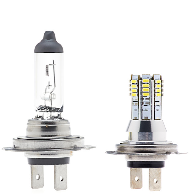
A 'new' style H7 LED capable of better mimicking the point source of the Tungsten filament.


Two more designs that attempt to recreate a point source illumination. I particularly like the 'trumpet' design of the first one using the shaped 'trumpets' to produce the point source by concentrating the LED output..

I intend to purchase a pair of these 'trumpet' designs just to see....

All of the above H7 LED bulbs are direct replacements. As far as I can ascertain they all claim to have higher Lumen counts then Tungsten/Halogen but with less then a third of the power consumption.

A standard Tungsten headlamp bulb is rated at 55watt and produces 1000 Lumens. 

A Halogen ('Nightbreaker') can put out 1500 Lumens

All of the above LED bulbs are capable of matching the Lumen output for a third of the wattage, and would be ideal for use on HX, but there are available LED bulbs with much higher Lumen outputs...


Three images of super bright LED bulbs that probably can produce a better 'point source' then the other ones above.

They are all rated with higher wattage and Lumen output then the others, typically 30 watt plus and around 3000 Lumens. 

All that extra power means these units run at a  much higher temperature and because of that they need their own on-board cooling mechanism. This is contained in those 'plant-bulb' bases which house the heat sink or even a motorised fan. The physicality brings extra spatial requirements for their installing and also reflects in their price point.

I have seen this type of LED 'luminaire' asking around £50 to be taken home.....

Finally, the 'point source' revolution has even reached to the H11 fitment used on HX for its front fog lamps....
...saving those pennies as I write .....

Wednesday 7 December 2016

Td5 D2 engine - EGR / Exhaust Cooler

A while ago I removed the EGR valve from HX. That was an easy and well documented modification helping the engine to breath more clean cooler air which all helps with the internal combustion.

Removing the EGR valve leaves a handful of 'open' vacuum lines that need to be plugged or removed entirely. The opening and closing of the valves is controlled by vacuum pressure which is supplied by the vacuum pump that is mounted on the front of the alternator.

Failure to block-off these vac lines can lead to failure of the brake-servo which also uses vacuum pressure from the pump. This is a safety critical concern and must be competently addressed.

HX is a '15P' Td5 with the additional fitted exhaust cooler mounted on the front of the engine directly in front of the cylinder head. In the following diagram, the exhaust cooler is labelled '3' and the fluted pipes either side connect it to the exhaust manifold on one side and the EGR valve (1) on the other. Part no.18 is the equivalent pipework on a non '15P' TD5

As well as having to seal the end of the cooler which has a direct feed from the hot exhaust manifold, the cooling function of the unit is provided by its built in water jacket connected by pipework to the engine cooling circuit. These coolant supply pipes need to be removed and the integrity of the cooling circuit must be maintained. Simply plugging their ends is not enough as that will only create 'dead' ends in the cooling circuit flow.


Two views of the exhaust cooler removed from a TD5 engine. The small bore connections for the water jacket can be easily seen and the last photo even shows the flimsy plastic pipework that I needed to replace. 

Sections of the factory fitted pipework used to service the exhaust cooler are made from a thin bore plastic that in time will just go brittle, crack and fail causing loss of the engine coolant and potentially cooking the engine.

I know this from experience as it was the first problem HX threw at me. I was tracing the source of a coolant leak and was shocked to find that the pipe was plastic and alarmed at how it just cracked under finger pressure!! I had to swap out a section of it with some rubber hose and even now it remains thus... 

It was always my intention to remove the exhaust cooler water pipes and that led me to an investigation of the routing of the cooling system pipes on the TD5 engine and to plan how to re-route the piping. Well that was a few years ago and the time has come to revisit that idea.

Rave is pretty good at describing the engine cooling system and even has diagrams of the differing systems and a very handy 'flow' diagram that displays the directional flow of water through the pipework.

Using these diagrams it is easy to see that the modification requires the exhaust cooler inlet and outlet to be connected together to effectively by-pass the exhaust cooler. The only question is where and how to do this .....


In the above diagram, the 'euro 3' 15P engine cooling system is shown while inset 'A' shows the original configuration. Part no.6 and 39 have the same function being the metal pipe that is attached to the rear of the engine block and fed by the oil cooler mounted below the turbo. Part 37 is a shaped rubber pipe running from the end of 6 direct to the inlet on the exhaust cooler 34. This pipe needs to be re-routed to connect to the coolant reservoir where 36 is shown to connect to the coolant reservoir.  This pipe, 36 is the thin brittle plastic one prone to failure.....

Figure it's best to use rubber hose for this but there is some tight bends to be made so raiding the spares box for suitably shaped lengths of hose is a must.... Not a hundred percent sure of the bore measurements, they look like they are different at each end but that is easily overcome with adaptors.

The above diagram from Rave shows the directional flow of coolant through all the pipework on both versions of the TD5. 

Apart from the obvious difference with the exhaust cooler install, careful study reveals differences in the radiator and coolant reservoir as regards the pipework attachment points. It is not possible to convert a 15P engine cooling system to the earlier cooling system without changing the radiator and coolant reservoir to match...  This should be born in mind if any spares are needed in the future..

Finally for now, a shot from the Web showing an exhaust cooler on the front of a TD5 engine. The fan has been removed along with the rocker cover and the injector harness. The black circular plug on the cylinder head immediately behind the exhaust cooler is the source of an oil leak on HX , but that's another story ..


Another blog deals with what happened when Hx started leaking coolant from the exhaust cooler return pipe and how I fabricated the by-pass hose discussed above...


Thursday 1 December 2016

Td5 D2 Seats - Heating Elements

FRONT SEAT HEATING ELEMENTS. 


Pictured above is the heating element for a front seat 'squab' which is the upright back of the seat. Each front seat has two heating elements, one on the squab and another on the cushion. The white connector shown above simply plugs into the lead from the cushion element which itself then plugs into the fitted vehicle loom via the brown connector under the seat frame shown below.


All Discovery models have this brown connector under each front seat. It is wired into the vehicle loom and is used to supply power to the seat heating elements and the electric seat motors (if fitted).

Hx currently has black, fabric-covered, non-heated 
manual seats. It's electrical loom contains the wiring and connectors to enable the manual heated seat option to be easily installed.

Originally I was just going to install the 'manual' heated seat option and bought the above 'manual' element off E-bay. The plan has now changed to install fully electric seats and the above 'manual' element will no longer be suitable....

Although the heating pads for both the 'manual' and 'electric' seats are physically similar they do differ in their resistance and heating cycles and as a result of this they have differing part numbers ..

HGT500020   -  Seat cushion - Electric seat 
HGT500030   -  Seat squab - Electric seat

HGT500040   -  Seat cushion - Manual seat 
HGT500050   -  Seat squab - Manual seat   


These numbers are printed onto the element's fabric covering along with the word 'manual' or 'electric' to avoid confusion. It is important not to mix the heat pads together as that will lead to electrical inefficiencies and the potential of fire and burns!

Land Rover even issued a 'Technical Bulletin No 0130' back in 2004 that addressed this issue and the problem of local 'hot spots' on the seat cushion. ..


THE HEATING CYCLE. 

The operating temperatures are set by the factory and are not variable by the user. I believe that the lower target is 26°C and the upper target is 36°C.

Heated seat elements on an 'electric' seat are governed by a variable resistor/thermostat that automatically maintains or 'modulates' the heating output by varying the current draw as required in order to keep the operating temperature at the defined target.

The 'manual' heated seat is controlled by a simple thermostat that cuts power when the factory set 'max' temp value has been attained. When the lower 'min' temp is reached, the thermostat switches the power back on and the cycle repeats. 

I have read about the current draw being 150 watt which is a lot! The 'Owners Handbook' states that the heated seat option should only be used when the engine is running as the current is then supplied by the alternator. I don't know if that 150 watt figure is for both seats or just one. It also points to the need for the alternator charging circuits and the battery to be in a good healthy condition. I am now wondering what the rated output is for the fitted alternator?


CONSTRUCTION AND FITTING. 

Here are some close ups of the heating element sandwiched between the fabric layers. I photographed them back lit on a window to reveal their structure  


Any malfunction of the heating pads is nearly always due to breaks or creases in the thin wire element or in the connecting lead between the two elements on the seat. The wire is very thin and subject to a lifetime of flexing and compressing particularly on the drivers seat cushion.

There are many online accounts of repairs being undertaken to broken heating element wires by simply soldering and insulating the breakage. Most of the repairs can be done on the vehicle, but removing the seat is the preferred option as it allows greater access to remove the covers and foam pads.

The photo below shows the fitted position of an element on a squab cushion. It is attached to the foam cushion and lies beneath the outer covering. The method of fixing is just fabric glue, one side of the element is 'sticky-backed'. 

The connecting wire can be seen to be routed behind the base of the 'squab' foam. The seat 'cushion' is not shown. The cut-out sections on the element and the visible holes on the foam panel are to locate the 'hog-rings' that secure the covering to the cushion and the cushion to the seat frame.


Update  -  I keep meaning to uploadand insert the LR technical info sheets regarding faulty seat heat pads..  one day I will get around to figuring how to..!