Wednesday 31 May 2017

Td5 D2 engine - Front Camshaft Seal.

This is a common problem on the Td5 engine and the  removal and replacement is well documented over many sites on the web.

Hx has been suffering from this for many years. I bought the replacement seal some time ago but only now have got around to doing it on the back of by-passing the exhaust cooler...


The Camshaft Front Oil Seal is a large 7 cm plastic plug fitted with a thick rubber 'o-ring' seal for a tight interference fit. Over time the rubber o-ring will perish and lose its radius and then engine oil can get past and dribble out and down the cylinder head and gunk everything up!


The congealed leaky oil can easily be seen below the seal in the above photos.

Removal begins by first undoing the two 8 mm bolts that secure the nearby electrical harness either side of the fitted seal to gain better access.

Hx is a 15P Td5 so it is fitted with an exhaust cooler mounted just below the seal location. It is possible to remove the seal with the cooler still in place. My recent work to by-pass the exhaust cooler meant that the hoses for the cooler are now removed so access to the seal is easier.

I cleaned up as much of the gunk from around the failed seal as I could. Be careful not to dislodge bits of the oily gunk onto the belt pulleys which are nearby.

Removal of the failed seal was easy. It was not a tight fit (which indicates a poor performing seal) and it was possible to winkle it out with my fingers.

I was a bit surprised at the size of the 'air-gap' between the end of the camshaft and the casing of the cylinder head. I guess I was expecting some sort of oilway to be right behind the seal ..?

I cleaned up the mounting face and then smeared clean engine oil onto the new seal and the seal housing in the cylinder head.

The new seal was carefully positioned square on to the head and then initially 'popped' by hand into its aperture. 

I was relieved at how tight it was going in. I used a suitable metal strip to winkle the new seal fully home using the body of the exhaust cooler as a lever/fulcrum.

This was a simple 10 min job. Yet it took me 4 years to get around to do it!!


Two photos above show the removed seal after cleaning up. The thick O-ring can clearly be seen to have lost its radius and worn 'flat'.

Friday 26 May 2017

Td5 D2 engine - coolant leak ..EEK!!

Noticed a wet patch on the driveway yesterday just when I was going out. It was obvious that it was engine coolant from the look and feel of the residue. 

Looking under the bonnet, the coolant reservoir level had dropped and the pipework connecting the exhaust cooler on the front of the engine was wet and weeping.


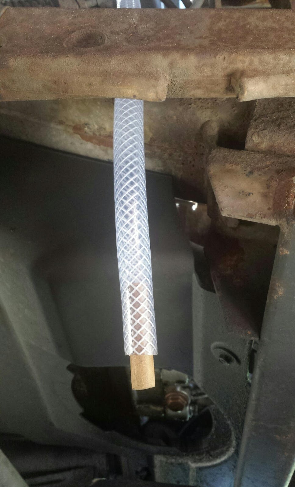
The thin pipe shown above is the source of the newly discovered leak. This is where the pipe tucks under the acoustic cover to connect to the exhaust cooler.


Two more views from under the front of Hx looking at the steering gear and undertray. 

The extent of the leak can be judged from the staining on the components. At first glance, it would seem that the steering box has sprung an oil leak.

Only yesterday when I replaced the engine acoustic cover, I noticed that the hose which connects to the upper outlet on the exhaust cooler had somehow moved closer to the nearby spinning fan blades. There was no obvious signs of leakage but with a weird sense of premonition I recall thinking it was about to give up as I secured it back up under the cover.

And there is history of this happening before...

When ownership began years ago, the first issue was a coolant leak from the very same section of pipe. I recall at the time being surprised that this section of pipework was made from thin wall plastic that given time and temp just goes brittle and cracks. It is a known trouble spot on the Td5.

Back then, I repaired it by cutting out the affected section and replacing it with suitable rubber hose. That repair lasted till today.

Now, rather then just repair this section of pipe again, I propose to drain down the cooling system and remove the exhaust cooler plumbing completely. This will require some fabricating of a suitable hose to by-pass the cooler and maintain the integrity of the engine cooling circuit. 

Also, it will make sense to renew the OAT coolant. It has a 5 year life which is well overdue for replacement.


DRAINING THE COOLANT..

This view, looking up from beneath the front of the engine, shows the circular access cover removed from the undertray. The bolt head visible is the drain plug for the cooling system. Its a 13mm bolt and the pipe is metal at this point.

I mainly followed the Rave procedure for draining the engine coolant, although I left the reservoir cap on till the drain plug bolt was removed to try to stem the rapid flow. The 13mm drain bolt was very tight and I had to use a big breaker bar to crack it loose.

I used a large drip tray to collect the antifreeze as I wanted to measure just how much came out. In the end just under 7 litre drained out. 


COOLANT TYPE AND CAPACITY .

Td5 engines use red coloured OAT antifreeze. OAT stands for Organic Additive (Acid) Technology. It offers better performance and protection then the blue ethylene glycol variants and it has a longer working life. 

The two formulations are not compatible and must never be mixed together as the outcome can produce a kind of chemical jelly.

Rave gives two figures for the engine coolant capacity. 8 litres for a refill and 13 litres if filling from 'dry'..? I am assuming the 13 litre figure is what the factory originally put in and the 8 litre figure is for service intervals like now. The dilution is 50% and as I have 5 litre of concentrate that means I have 10 litre max.

Mentioned earlier that I drained nearly 7 Ltr from the system. Reckon that means Hx lost over a litre to the 'leak', I recall the coolant reservoir level was well below its normal level and it will be interesting to see how much goes back in!


BY-PASSING THE EXHAUST COOLER .

In a previous post 'Cleaning up the EGR Removal' I outlined my intent regarding the exhaust cooler plumbing and gave some background into doing so. I will concentrate here on the hose fabrication after a little re-cap...


This is the exhaust cooler from a Td5 15P engine. It is mounted to the front of the cylinder head. Two hose connections are shown, the lower one is the inlet and is of normal rubber construction. The upper connection (still attached in above photo) is the outlet that routes to the coolant tank. This pipe is a hybrid of rubber and thin-walled plastic and is prone to leaking.

I had already replaced a section of the plastic pipe that had failed on Hx, but I have to report that the same section (rubber this time) has failed again causing the current leak.

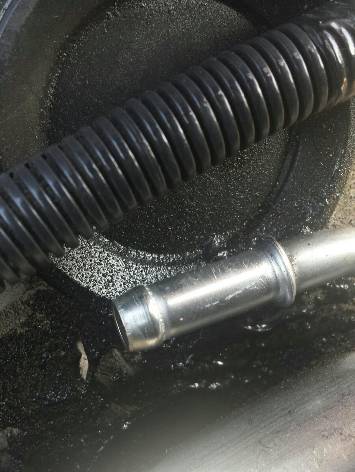
Here is the location of the current leak. This pipe can be seen in the first photo of this blog.

Clearly something has been rubbing against this pipe and causing the hole to appear on the left. It is just a 'pinhole', but heat and pressure will inevitably do its thing.

I wrote earlier about the possibility of contact with the nearby fan blades, but it could also have been rubbing on another component. Either way it has resulted in taking Hx off the road.


FABRICATING A NEW HOSE

Time to delve into the bag of bits ..

From the above chaos, comes some order. Have to admit that I really enjoy dickin around with this sort of thing. Lots of time spent looking, planning, and test fitting finally arrives at the solution!

This is the 'new' coolant hose custom designed and fabricated to by-pass the exhaust cooler on the Td5 engine. All the bends and turns are 'natural' and chosen on purpose.


All components are from the spares bin including the in-line plastic connectors. These actually came from the hoses that were removed from Hx.
  
They are a tight fit into the small-bore hose, but I had to leave the 'stump' of the original hose on the fluted end of one of the connectors in order to get a tight fit into the larger bore hose. 

The finished hose, still in two parts but with clips and connectors fitted.


Close up of the connection where the internal bore size changes. This change of bore size mirrors the original install which also uses pipes of differing bore sizes. I would like to know why this is so? Maybe it is down to fluid dynamics and the need to make sure that the flow rate is maintained?


FITTING THE NEW PIPEWORK.

First connection is to the end of the metal pipe that runs around the back of the engine block.

Tracing the path of the original exhaust cooler supply hose will reveal this location beneath the fuel cooler/ inlet manifold. The thicker end of the new pipework easily connects here and directs the flow upward towards the Coolant Reservoir. The thinner section of pipework then connects direct to the Coolant Reservoir itself.

This new pipe run was easily fitted to the engine. I tried to take some photos of it fully installed on the engine but it is difficult to show clearly in a photo.


REFILLING THE COOLANT.

Rave recommends to flush the system with running water once it is drained down. I elected not to do this fearing it would only dilute any remaining coolant that was left inside the engine and therefore dilute any new solution that would be added.

I am a bit confused by the Rave figures of 13 litres for the 'dry' capacity and yet only 8 litre for the refill..? 

That would seem to suggest that only 8 litres will drain out of a previously filled cooling system. I was careful to collect the drained coolant from Hx just to see how much came out as well as look at its condition. In total just under 7 litre was drained out but that doesn't account for the leaked volume. So its safe to say that without the leak I would have drained out 8 litre.

Before re-filling commences the drain plug has to go back on. I wrapped a couple of turns of PTFE tape onto the threads and torqued it hand tight for now.

There is a vent plug that needs to be opened on the top radiator hose during the refilling procedure. Rave recommends that coolant is added to the reservoir until it emerges from this vent. 

Curiously, Rave also recommends raising the physical level of the reservoir by 4 inches during re-filling. It will just unclip from its position and it is important to refill the system thus. I can only assume it helps to remove any air pockets internally?..

I used a one litre water bottle to mix the coolant and water in handy litre measures. Use of a small funnel helped to avoid spills. 

I filled the reservoir up to its maximum level without any fluid emerging from the vent hole. I then started the engine and shortly after that the coolant emerged from the vent hole. I quickly tightened the vent plug up to stop the flow. I then stopped the engine and checked all the new hose connections for leaks. 

The level of coolant in the reservoir had dropped again so I topped it back up to the max level and went for a little drive to warm the engine up and re-checked everything again.

Pleased to say there are no more leaks.

The level will be checked and topped up over the coming days just to be sure, but things are looking good so far...

UPDATE : The next day I checked the reservoir level which had dropped slightly and topped it up with the remaining mix from the other day. This means in total 7 litres of coolant were replaced in the engine.

All the new hose connections and the drain plug were dry. I will check again in a few days before striking this off the 'to-do' list.


see also  -  ' Td5 EGR / Cooler removal '


Wednesday 24 May 2017

Td5 D2 engine - Turbo Wastegate (2)

ADJUSTING THE BOOST SETTING. (23/05/17)

The boost setting on the Turbo Actuator was adjusted for the second time. The initial 'feel' from the little test drive was promising, but I really need to assess it by logging data onto the Nanocom.

The intention today was to increase the MAP (Manifold Absolute Pressure) closer to the target value of 242 K/pa.

My initial fear that I had put the boost setting into 'overboost' proved unfounded and even now I'm thinking that the boost has yet more to give.

In an earlier post, I described how to adjust the onset of the boost using the knurled adjuster on the Actuator rod.

Initially, when I originally removed the Turbo Actuator from the engine, I carefully counted and wrote down the number of threads visible in front of the adjuster locknut.


This is the drawing I made detailing the initial setting of 13 threads and noting what I call the 'first adjustment' of 12 threads. It was easy to make this adjustment with the actuator removed from the engine, but it is possible to do it on the engine. The black knurled adjuster behind the locknut should turn under firm finger and thumb pressure.


First Adjustment - 12 threads

Placing a small piece of blue tape on the adjuster nut really helps to determine the movement of the nut during adjustment. The adjustment of the nut can accurately be controlled to a quarter, half, or full turn. The necessary adjustment can really be that fine.

This '12 threads' setting was combined with the install of the new MAF sensor and then road-tested with the Nanocom during the first four 'data log' sessions.(T1-T4).

Figures from those tests show a maximum developed MAP value of 219 K/pa (T4/198)

The 'target' MAP value is 242 K/pa and it was decided to get closer to that by adjusting the Actuator rod initially by one thread..


Second Adjustment - 11 threads.

It should be noted that this adjustment was carried out after the ProVent engine breather was installed. Also, a couple of weeks had passed since the first earlier adjustment in order to get a better feel for the performance.

I was very weary that this adjustment would send the engine into overboost mode and the initial test drive would produce the jittery fuel cut-off symptom at full-boost. Thankfully this did not happen.

I now need to connect the Nanocom and do another test drive/data log to determine what the maximum MAP is now. At this stage, I would expect to see an increase in the MAP figure and it should be possible to then gauge how much to turn the adjuster to get it closer to the target of 242k/pa.

Did not connect the Nanocom for a few weeks and the test run's I did (T5, T6) did not produce the results I was expecting. There was only a marginal gain in the MAP figure, but I have to say that the test conditions were not the same, so I am prepared to ignore these test runs MAP wise.

I wrote more about these tests in 'Td5 MGMT - MAP Test 4'.  Looking back on the numbers and the marginal improvement therein, I decided to revise the test route to concentrate on getting the engine to 3k rpm in 4th gear. The outcomes of which was to look for a different test route, and to adjust the Boost Setting once again!....


Third Adjustment - 10 threads

This was done on 30/06/17 and the first initial drive was encouraging. There was no overboost and the turbo pick up seemed to be starting earlier. The only way to confirm this is with the Nanocom.

Ran around with this setting for a few weeks to get a feel for it before connecting the Nanocom and recording the figures in T7.

Made use of a new test route and in general was pleased with the response of the engine, but dismayed to find the MAP figures still not climbing as I expected.

Data in T7 for the MAP shows no appreciable gain over T6 so it's back to the drawing board.

Started to pay attention to the Inlet Manifold Temp. There is a lot more data captured in these test runs then just MAP figures and I'm trying to get an idea of what the Intercooler is doing in terms of temperature drop of the charge air in a given set of conditions.


Fourth Adjustment  -  9 threads 

This was done on 20/07/17 following on from the results and experience of the previous adjustments. 

The Nanocom test on 10 threads (T7) did not produce the expected figures but that may have been due to gearing and a new test route. I elected to adjust some more and noted that the physical adjustment was a bit harder this time and I had to carefully use a wrench on the knurled adjuster.

Initial drive on the road is promising. The boost from the Turbo sure feels stronger and there is still no Overboost flutter. If the Nanocom doesn't show MAP moving up over 220kpa under boost this time I will be shocked!

13th Sept 2017 - Finally got around to another test run with the Nanocom. I have called it T8 and the results were as follows. 

The highest MAP value obtained was 223k/pa. This was achieved in 3rd gear under load at 2414rpm.

That's a gain of 3k/pa but once again it just points to more being available. ...


Fifth adjustment  -  8 threads. 

19th Sept 2017 - Did this on and having loosened the locknut, I sprayed some WD onto the threads and adjuster. This seemed to help as the knurled adjuster moved under finger pressure again. It was left at 8 threads for a Road test and the Nanocom test run.

The Nanocom test (T9) was done a few days later on 23/09/17. I drove around for a few days to get a feel for the new setting. There is no still overboost flutter, and performance when pushed feels better, but I am beginning to doubt the validity of my judgement and will look to the figures obtained under test conditions.

When analysed, the figures from T9 do not show an increase in the max MAP figure. 

The highest MAP figure obtained was 223.75k/pa (T9-170). That is .02k/pa less then that achieved on T8.  Have to admit to being a bit disappointed at that outcome, but I guess it just shows that these things aren't simply a linear progression.

I will double check the wastegate settings and consider adjusting some more..

Starting to wonder if other engine parameters are having an effect now?


Sixth adjustment  -  Seven threads 

27th Sept 2017  -  Dismayed at the 'standstill' result with the previous setting, I decided to press ahead and continue adjusting the thread length to increase the K/pa value on boost.

Once again the adjuster was turned by finger pressure after a squirt of WD40. The previously applied piece of blue tape finally came adrift, probably from WD over-spray. A new piece was quickly installed though it must be stated that it's use is just as a guide/datum mark. A close up photo is used to count the visible threads before and after adjustment.

I have driven around for a few weeks now with this setting and sure do feel a positive differrence in the driveability. I am a lot more confident moving off at road junctions and at roundabouts. Overtaking is more confidently executed. 

I have decided to continue to increase the boost and now favor an extended on-road drive-ability test against the Nanocom circui' tests. I guess that a combination of the two is the better option, but for now, I will just go ahead and adjust the Actuator rod one more time. 


..Seventh adjustment - Six threads...

20th Oct 2017  -  Recent thinking has moved towards adjusting the wastegate without testing the current setting with the Nanocom. 

This was mostly done freehand, the last quarter turn needed the wrench applied to the knurled nut. No WD40 was used. 

Like to think that I am gaining performance. The question is how much is still untapped? 

Next month is MOT time and I am already wondering if this is doing anything to the emissions..??

Sunday 7 May 2017

Td5 D2 engine - Fitting the ProVent (4)

The final stage of installing the ProVent was to connect the unit into the engine 'breather' circuit.

I thought the hardest part of the install would be to mount the ProVent body in the engine bay.

In the end, routing the hoses, connecting them together and ensuring they avoided other components proved to be the more time consuming.


I decided to remove the factory fitted 'Depression Control Valve' from the Turbo Intake hose. The ProVent unit comes complete with its own depression valve built in. In doing so, I freed up some space above the intake hose allowing the new plumbing to be better routed. 

The fitted Depression Control Valve was replaced by a 19mm plastic elbow connector that allows direct connection to the turbo intake hose as shown in the above photo.

The original factory fitted rocker cover breather hose was used in its entirety, there was no need to cut or modify it. The new section of hose simply joined onto the end via a straight plastic 19 mm connector. Doing it this way means that the original configuration can be re-installed and the ProVent removed easily should the need arise in the future.

Also, using the full length of the original fitted Rocker Cover Breather hose ensured that the routing avoided any potential heat or rubbing points.

The curve of the new hose shown above is the result of the molding with hot water. The curve is now natural and there is no tension on it. I was particularly pleased at this outcome!


Two views of the fitted connections onto the ProVent unit. The blue elbow connector was a last-minute necessary addition whose procurement caused a lot of hassle, but in the end it all worked out fine.

The blue and black connectors are also 'reducers'. This means that one end of the hose (the ProVent end) is 25MM ID and the other end where the clear hose attaches is 19mm ID.

The ProVent mounting clamp is designed to allow the body of the ProVent to be rotated horizontally to allow greater flexibility in its instillation. A last minute adjustment to that angle really helped with the routing of the inlet hose.

Also visible above is the ProVent's built-in depression control valve which is the side mounted circular projection near where the blue hose attaches. In addition to this control valve, the ProVent unit also has a built-in safety valve in the lid section that will open if the engine blow-by gas pressure gets too high.

The final connection was on the base of the ProVent where the oil drain-off outlet is located. It is a 13mm connection and I simply ran a suitable length of plastic tube vertically downward and secured it to the outside of the chassis rail. 

The end of this hose needs to be 'capped' as leaving it open to the atmosphere will disturb the airflow balance through the unit. Options are to fit a one-way valve/stopcock drain to its end or fabricate a bung.


I choose the cheaper option and used a spare piece of wooden dowel that was a nice tight fit in the open end of the hose. The image above was taken from underneath HX and shows a section of the front nearside chassis rail and axle sway arm. I feel the tube needs to be trimmed shorter to avoid grounding issues. Trimming it back to the chassis rail would be best.

Research online points to low levels of seperated oil being emitted from the drain and having a transparent hose will allow a visual inspection of any recovered oil building up in there over time.

The ProVent manufacturers are 'Mann Hummel' and they make available lots of information and specifications about the ProVent range via their website. It is required reading and even mentions the option of plumbing the drain back into the engine sump to ensure total recovery of oil from the by-pass gasses....

Here are the final costs...!! (some clips,hose,straight reducer and straight connector remain surplus)

ProVent 200 - £98.50 - 'MFE Wrexham' (E-bay)

Silicone Hoses  -  'Demon Motorsport' (E-bay)
All are 'reducers' 25mm to 19mm
Straight x2  -  £10.98
90° elbow  x1  -  £7.19

Plastic Connectors  -  'Adv Fluid Sol' (E-bay)
19mm straight x3  -  £4.74
19mm elbow x2  -  £2.52

Plastic Hose  -  'Mirfield' cowboys via (E-bay)
19mm x1mtr  -  £4.22
13mm X 500mm  -  £2.52  

Hose clips  -  'B+M'
assorted sizes x8  -  £2.99.

TOTAL  -  £134.60


ProVent 200 installed on the Td5 Discovery.