Monday 18 December 2017

Td5 D2 electrics - facelift headlights

HX is a 2002 model D2 and as such is fitted with the so-called 'facelift' light units.


This was part of Land Rover's desire to tie-in design elements across their whole range of vehicles (apart from Defender). Other populist names for them are 'frog eyes' or 'four pots' but the term 'facelift' seems to be a universal moniker.

Much more subtle changes were made to the rear light clusters at the same time. The bumper mounted light units now contain the reverse and fog lamps, while the indicators were moved from the bumper up to the body mounted light fitting. Although the location and physicality of the rear light clusters did not change, the lens colours and the wiring looms certainly did.

It is possible to 'upgrade' early D2 light units to the later 'facelift' lights, but it is not as straightforward as it would perhaps appear to be. To install the facelift headlamps onto an early D2 and to do it properly requires quite a bit of work...  The wiring harness is completely different and the slam panel metal will need cutting back or even replacing, but that doesn't put peeps off doing it!


THEFT AND WANDERING AROUND LOST.

Creating a demand for the front 'facelift' lamps has fuelled a supply shortage. They are still readily available to buy new, but their cost is truly extortionate! Its sadly inevitable that the criminal element amongst us can see a market to exploit by robbing Pete to sell on to Paul.

Theft of the headlamp units on any Discovery is nothing new. Early D2 and D1 share the same headlamp mounting which was literally a push on/ pull off design. (A good example of the LR 'that'll do' mantra!) It's not hard to see how that leads to expectations that the 'facelift' units mount and dismount with the same ease.

Reading and speaking to D2 owners that have suffered this theft all echo their shock and anger at the speed and brazenness of the theft. The light units are literally ripped off the bodywork and the looms cut free. Almost always this is done without even opening the bonnet. To Hell with the Rave procedure! It's almost like someone knows how to go about doing this..

Anyone who's ever changed a light bulb on a facelift D2 knows the hastle. Firstly, you need to open the bonnet, remove the centre grill, and then undo and remove the three screw bolts holding the lamp unit to the body before moving the entire lamp unit forward to get access to the bulb covers. Doing all that surely shows how it's not possible to just 'pull-off' the light unit?? But then again I ain't thinking like a Perp. Just how is it possible to swiftly snatch the lamp units from the body without even opening the bonnet..??

Well, one thing I can state for sure, if you are ever offered or buy a facelift lamp unit that has ANY damage to the mounting brackets or locating lugs then it most certainly has been forcibly removed from it's mother Disco!

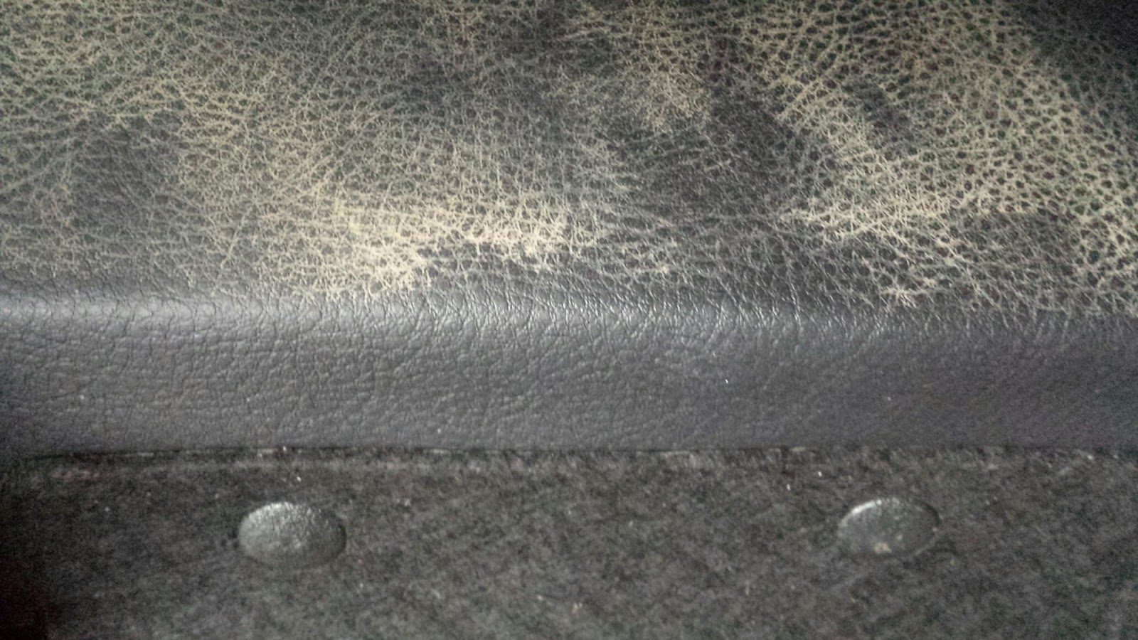
The body-coloured plastic finishing strip on the bottom of the lamp unit also plays a part in all of this skull-duggery. There is no way that this strip can just 'fall-off' or become cracked or damaged unless some Perp has had a go at removing it. It appears that removing the finishing strip will allow the Perp to get a good grip on the lamp body behind that strip.
So if you ever return to your 'facelift' Disco and find the finishing strip damaged or missing you can be sure that some Twat has had a go at nicking the lamp unit.


ATTACHMENT POINTS.

Not counting the loom, there are four attachment points holding the lamp unit to the bodywork. Three of them are screw bolts but only one of those attaches directly to the metal bodywork. The two bolts on the upper surface are only accessible with the bonnet open. They secure the lamp unit to the plastic adaptor plate that in turn is bolted to the slam panel..


The above photo shows one of the metal collets moulded into the top surface of the lamp unit that the upper screw bolts attach to..

The metal bracket on the inner side of the lamp unit provides a strong secure connection direct to the metal bodywork..


The fourth mounting point is really just a guide/ positioning pin that locates the lamp unit into a body mounted rubber grommet!

The 9-pin loom connector can be a pain to remove at the best of times! It's no surprise that Crims just chop through the wires for a speedy removal. (But, as I said earlier, the loom connector will be needed for a retrofit).

Looking at the 'cavity' revealed when the lamp unit is removed, it quickly becomes apparent that there is no physical connection between the bottom of the lamp unit and any part of the bumper or lower bodywork... The importance of the design of the plastic 'finishing' strip soon becomes obvious!


This is the RH headlight cavity showing the upper surface of the bumper and the vertical face of the bodywork mounting panel. The rubber grommet can be seen on the left and over by the black plastic grill can be seen the raised bolthole for the inner screw-bolt which is perhaps the strongest attachment point. (The enclosed cavity below the bumper is huge!)


The same area on the LH side, but the cavity below the bumper on this side is where the screen-wash bottle is mounted. The mounting bracket for the wash bottle fits into a shaped recess on the rear of the lamp unit but it is not attached to it..

Another view of the lower LH headlamp mountings. The rubber grommet can be seen on the right and the raised bolthole can be seen on the opposite side by the black grill.


ADDITIONAL SECURITY MEASURES

Lens guards and grills are available, mainly designed from the concept of off-roading, for which (to my eye) the light units are not. Mounting them requires the wing panel to be drilled for some self-tapping screws which have to be easily removed to allow for bulb-changing. Perhaps visually they provide a visual deterrent to a Perp, forcing them to seek an easier target?

I have also seen worried owners fitting some homemade metal straps and even cable-ties to help increase the physical security of the light-units. Cable-ties are great at holding things together and have been part of the 'emergency' kit for years, but all it takes is just one snip..

Insurance companies and law enforcement agencies often recommend 'security marking' of personal property to aid recovery after a theft or burglary. It's a mute point and is something I have never done before.

Marking personal property to appease the threat of theft somehow only makes that theft more inevitable and I feel it is surrendering to the creeping tide of anti-social shite..

So out came the Dremmel(!) and I set too with a handy engraving/carving bit. I cut the full registration of Hx onto each light unit in two separate locations. As I was doing this, I figured that these marks can just be grinded away for sure, but it sure would look ugly.

Thought about etching the reg onto the front lens; but decided against that. I intend to get a UV marker pen to write the reg where it will be visible when mounted to the vehicle..

ALARMING THE LIGHT FITTINGS.

While reading up about securing the 'facelift' headlamps, I found a reference to extending the fitted alarm system to 'cover' the lights.

This naturally got me interested and I set about investigating the possibilities.

The alarm system on a D2 includes an often overlooked bonnet switch that protects it from a forced entry. That's probably why Perps don't open the bonnet when stealing the lights (?).

There is a simple plunger type switch mounted by the air box that receives a voltage signal from the BCU when 'armed'. The closed bonnet holds the plunger contacts 'open' and if released, the contacts are 'closed' and the signal earthed. The BCU detects this and fires the alarm.

It is a simple task to extend the system to cover each light unit with its own 'plunger' type switch. The hardest part will be sourcing suitable switches and deciding the best place to mount them on the bodywork. My plan is to use the plastic trim as the trigger point figuring that it might just save the lamp unit providing the owner is within earshot..  

Searching around E-bay for suitable switches soon threw up these simple plastic plunger types that will do for the first attempt at alarming the light units.


CLEANING THE PLASTIC LENSES

Comparing the two light units together, it was readily apparent that the clear plastic cover of one of the units (the RH side) was a lot more 'cloudy' in appearance then the other one. I began to doubt if one unit was newer then the other one, or whether the effected unit was actually cloudy on the inside surface of the lens.


To remove the cloudy oxidation I used some 'Halfords' rubbing compound (toothpaste does the same job) applied with a clean damp rag and some elbow grease working a small area at a time and regularly cleaning it off to compare the progress.

Progress was swift and the reflective shine quickly returned although it still did not match the other unit. At this point I mounted a soft woolly polishing mop onto an electric drill and gently polished the worked area.This brought the shine back brilliantly and both units now match each other for sparkle!


Much improved! A quick easy fix.


DISMANTLING THE LIGHT UNIT.

As I mentioned above, I could not be certain that the cloudy appearance of the outer, clear plastic 'lens' was actually on the outside or the inside surface. I looked at removing the clear plastic covering from the lamp body initially just to give the inside surfaces a good clean.

Removal of the clear cover is unfortunately not so straightforward. There are plenty of locating clips all around the base of the clear cover, but the main method of joining the two is via a factory applied mastic/butyl strip that seals and locates the two elements together.

It is possible to undo this bond but it requires the application of heat to melt and soften the mastic to enable the two surfaces to be gently separated.

Careful use of a heat gun or 'baking' the entire unit in an oven for ten min (225°) will soften the sealant, and the process needs to be repeated to re-seal the lamp units. I decided to not attempt doing this.


UPGRADING THE LIGHT BULBS

The light units (UK spec) have four separate bulb holders in them. They are all standard Tungsten or Tungsten/Halogen single filament bulbs in three fitments. The sidelight is a '501', the indicator is a 'P21' and the main and dipped headlights are 'H7' fittings.

I have found the standard 'H7' dipped and main beam bulbs to be perfectly adequate for the job. The only upgrade I have considered is swapping them for the higher output Tungsten (Osram Nightbreaker) or replacing them with LED equivalents.

The LED market is constantly evolving. It seems that every six months or so, new improved versions come along and prices drop. The equivalent light outputs (measured in Lumen's) are comparable and LED is beginning to out-perform Tungsten based filaments.

Conventional Tungsten Halogen bulbs will emit about 1300 to 1500 Lumens including the so-called 'Nightbreaker' types. All Tungsten filament bulbs gradually loose efficiency during their lifetime of usage. 

Most LEDs operate at a minimum of 2000 Lumens. Many are capable of 3000 Lumens and beyond. LED output remains constant throughout it's working life.

I believe that outputs of 3000 Lumens and above are not considered 'road legal' so care in their selection needs to be exercised. 

Although these brighter LEDs consume more power and generate more heat then an 'ordinary' LED, they still offer major savings in power consumption over Tungsten.

The lower levels of heat generated by a working LED can lead to the front cover of the light unit frosting over and in winter conditions snow and ice can easily build up on the outer surface severely reducing the performance of the headlight.

It would appear that the writing is on the wall for Tungsten bulbs in general as the EU is trying to get them banned from sale due to their higher energy use. That probably explains the continuing development of LED and I am curious as to whether newly built vehicles have any Tungsten based bulbs at all?.. 


Sunday 26 November 2017

Knowing the left from the right

Left-hand, Right-hand, Male, Female, Nearside, Offside, Driver-side, Passenger-side, it all gets a little confusing.

Recent work on replacing the seats, the switch-packs and associated wiring has thrown up issues about orientation when thinking about component location.
I personally tend to favour the designation 'nearside' and 'offside' in relation to a vehicle parked legally on the roadside. Big trouble here is that those labels relate to whether the vehicle is right-hand drive or left-hand drive.

Rave mostly talks about 'Left-hand' and 'Right-hand' and for clarification it states at the very beginning of the Rave manual that... 

"References to the LH or RH side given in this Manual are made when viewing the vehicle from the rear...".

This makes a lot of sense as it can be used for all markets whether they be right or left hand drive. There are still references to 'drivers side'  and 'passenger side' to be found and I guess they are hard to shift psychologically from whatever market you are in. It doesn't help my case that one of my Rave manuals is North American Spec. (NAS) or that some of the illustrations, usually for the interior components, are drawn from that perspective. ...


Recent work on the electric seat components highlighted the issue of orientation like never before! Given that a lot of work was done with the seats upside down, it was handy to see 'LH' or 'RH" stamped onto the bottom rail of the relevant seat frame. 


Thursday 16 November 2017

Td5 D2 Seats - Electric leather

As a treat for flying through the recent MOT,  I once again searched online for a leather interior to complete this ongoing upgrade. Thanks to E-bay, I managed to source a set of leather electric seats that where only 15 mile away for £200.

I have been looking around e-bay (and other sources) for Discovery interior's off and on for a long time. I already have all the switches, switch panels and wiring looms that I will need for the conversion.

Complete interiors for sale regularly appear on E-bay. Prices and conditions vary considerably, as do their locations. The added costs of postage and the prospect of damage in transit made me decide a local sale was the best option as I would prefer to collect in person.

Well, it all came together last week. I now own a set of heated electric black leather seats complete with armrests. They are in a good general condition and came from a 53 reg vehicle so are younger then Hx.

It should be possible to test the function of all the electrics before fitting. It's also a good opportunity to study the circuitry and workings of the system as well as give the leather a good clean before installing them into Hx.


MORE RESEARCH AND LEARNING

Spent a few hours trawling through Rave studying all the info about the electric seats. There was so much info available that I ended up printing it all out and arranging it in a file for easy reference. This particularly helped when trying to trace the wiring path of individual components on the circuit whilst reading the written descriptions of each circuit. 

First thing to learn was the identity and the location of all the electrical components mounted onto the seat frame. Everyone of the electrical connectors throughout the vehicle is identified by a (usually) unique number. Each side of the connector (male/female) is identified separately, the wires are colour coded and the terminal pin numbers are identified. There is also information about the 'gauge' or thickness of the wire and even the length of individual wires between the connections. 

Having a print-out of the circuit and the connectors made the task easy and there was plenty of space to write notes 'in the margins'. It's a big mind-fuck to start with, but with a bit of study it all starts to make sense!


POWER SUPPLY TO THE SEATS

I was keen to understand how and where the electric seat components get their electrical power supply and whether the wiring loom in Hx, (being a manual-seat version) needs to be modified.

I am already aware that the Body Control Unit (BCU) will need to be 'switched' via the Nanocom in order to provide a switched BCU- Earth path that will effectively enable the whole circuit to function, but my main concern is with the wiring to and from the 5-pin brown connector under each seat.

brown male connector C0751. 

Two views above showing the brown male 5-pin connector clip-mounted onto the underneath of the seat frame. The grey connector nearby is for all of the control switch functions. (see 'Td5 D2 Seats - Switch packs'). This brown male connector is identified on the schematics by the number C0751. The same number is used to identify this connector under both seats. Although the connector can house up to five terminals or 'pins', only four are used. The cable colour-codes, gauges and pin-outs on the actual connectors under the 'new' seats match the schematics. So things are on track.

Attention now turns to the matching brown connector that the C0751 connector will plug into. All D2 Discovery's will have a brown female 5-pin connector wired into the vehicle 'main harness' and it should be present underneath each front seat regardless of whether they are 'plugged in' or not. 

Hx thankfully has those connectors in its harness. They are unused because Hx has non-heated manual seats. Studying the colours and pin-outs from the schematics confirms that they will match up with the connectors (C0751) on the new seats. Connectivity is improving!, but it's hardly 'plug-n-play'!

These two identical fitted harness connectors are allocated different numbers. C0255 for the 'left-hand' seat and C0253 for the 'right-hand' seat.

Each one has four wires connected, the colour codes vary slightly but the functions and circuit paths are identical. So what do these four wires do..? 

Essentially, they supply the power and earth return paths to operate all the systems fitted to the seats.

Let's look at the LH Seat harness connector labelled 'C0255' in Rave's electrical library..


These images are taken from the Rave 'connector views' section of the electrical library. The last view represents a 'head-on' view into the connector. Rave labels the terminals as 'CAV' meaning 'cavity', but I prefer the term 'pin'.. 

The corresponding connector that plugs in here is C0751. All connector faces are a mirror image of their 'other half'. This arrangement ensures that all the pins match. I.e. Pin 1 on C0255 connects to Pin 1 on C0751. The colour coding of the cabling may change but it's function does not.

Pin 1  - The 12v supply direct from the LH seat heater switch on the centre console. This wire supplies the heating elements only.

Pin 2  - Common Earth return for the electric motors and the heater elements.

Pin 4  - Earth path from the power seat relay mounted on the seat frame to the Body Control Unit on board Hx. This connection governs the whole system and is why the BCU needs to be interrogated by a Nanocom/ Testbook device in order to program the BCU to 'earth' the relay and close its contacts to supply power (from Pin 5) onwards to the electric motors.

Pin 5  - The 12v supply to the Power Seat Relay mounted under the seat frame. From there it connects power to all the electric motors and pump via the 'satellite' fuse box (40amp) and the seat switch pack. It does NOT supply/power the heater elements. 

NOTE: There is no wire/cable in pin/cav 3.


BENCH TESTING THE SEAT FUNCTIONS.

Feel it's important to test all the functions of each electric seat before mounting it into Hx. Armed with the above info, it becomes possible to work out how to 'bench-test' the electric seats by connecting an independent 12v supply to the relevant pins of the brown male connector (C0751) under each seat. 


The Rave electrical library does not have an illustration of the face of C0751 so I had to draw one myself. I also noted the actual colours of the cabling as well as their 'gauge'. Thicker wires generally carry more current then thinner wire.

To supply the power I will use a small AC/DC transformer, but a spare 12v battery could be used (provided its fully charged). I already have a bunch of test leads with insulated spade connectors on their ends that allow me to safely connect to selected pins inside a connector. With a bit of luck I should be able to confirm that all the seat functions are working before I get to install the seats in Hx..

Connecting Pin 2 and 4 to the negative terminal of the battery or transformer creates a functioning Earth path that will replicate the onboard BCU switching.

Connecting a 12v supply to pin 5 will allow, via the fitted switch pack, all the electric motors and the lumbar pump to be operated.

Connecting a 12v supply to pin 1 will operate the heater elements. Bear in mind this circuit will be switched 'live' by contact. The heater elements draw a lot of current. Rave states the total consumption as 115 Watts. I assume that to be with both seat heaters activated. 

I am now wondering if my little transformer can cope!? It only puts out 500mA max current which is not enough.

There is a 40 amp fuse that protects the electric seat motors and a separate 20 amp fuse that protects the seat heaters. That gives a rough indication of the current draw on those circuits.... a lot more then 500mA..!!

Well, the little transformer could barely move the back and forth motor and all the others just clicked away like a dead battery on a starter motor. Better to try with a spare 12v battery. 

When I eventually got hold of a spare 12v battery and connected it up as above, everything worked perfectly, first time!


CLEANING /INSPECTING THE NEW SEATS

As I said before, the new seats are in a generally good condition. A thorough inspection however does throw up concerns. There is a scratch on the rear of the Right Hand seat and a little nick on the lower base of the larger 2/3 rear seat. The rear armrest contains a pull-out cup holder and I noticed a piece of the finishing trim has snapped off, but I was only able to confirm this by comparing it to the same piece of trim on Hx. I may have to do a bit a swapping. 

The front drivers outboard seat bolster is a bit soft in terms of support but the leather cover is fine. This is the one area in any interior that gets all the wear from every time the driver gets in and out. Further investigation is needed. The drivers seat cushion currently in Hx is in the same condition. The passenger seat cushion is much more stronger and potentially could be swapped? 

In the past I have cleaned accidental spills and obvious dirt patches from leather by using a damp cloth or a wet-wipe. Research online talks about specialised cleaners and conditioners and I quickly was drawn to the 'Dodo Supernatural' leather cleaner which seems to be highly recommended in the motoring press.  In the meantime, I tackled some dried-on dirt with a wet-wipe and a clean micro-fibre cloth. 

This is the lower face of the rear seat, where a muddy shoe heel could make contact. I used the wet-wipe on the lower lip section with great effect and it left no visible deposit on the surface.  As an experiment, I used a wet-wipe on the apparently clean side panel of one of the rear head-rests just to see if any dirt would lift off. The worked panel did not look dirty at all yet the ingrained muck just lifted away. That was enough to convince me to get some Dodo cleaner to treat the rest of the seats. 

Must admit, I was initially more concerned with cleaning the 'workings' of the seats by getting rid of the fluff and debre that had gathered on the exposed threads and components of the mechanisms.


Two photos showing the extent of the dirt and fluff under the seats.

.. tbc ..

Saturday 4 November 2017

MOT DAY (AGAIN)

That time of year has come around again.

This will be the first MOT since I started altering the Turbo Wastegate. I tell myself that it should in theory have no effect on the engine emissions, but there's a nagging doubt back there. Hx now revs more freely then before and as the emission test is partly done at max rev it could create a spike at some point.

Confident there is no smoke emitted under acceleration, but it will remain to be seen. I even thought of winding back the wastegate adjustment! At least that could be a course of action if the emissions test proves problematic.

Having booked the test at the same garage, I dug out the current MOT noting its advisory of 'slight engine oil leak' and 'r/o/s tyre close to limit'. I was confident the fluid leak from the front of the engine had been resolved and I intend to swap that tyre with the spare before the test.

When removed and inspected, the damage visible on the tyre was a bit alarming....


The two photos above show the extent of the cut on the inside wall of the tyre with the second photo showing the 'cut' spreading across the thread to the outer wall.

Slap on the wrist time for me. There have been known issues with this tyre since ownership began as it slightly deflates on a weekly basis. 

This tyre will be replaced and I will thank myself for avoiding a blow-out. 

Other work in prep for the MOT mainly involved crawling under, wiping the transfer box and checking for any rust or loose and rattly components. Noticed that the gearbox casing looked to have developed a leak from the drain plug.

The engine fluid levels were checked. I topped up the coolant and the engine oil. The engine oil was just on the Min mark so I put half a litre in to bring the level up between the min and max mark on the dipstick.  

All the electrics were checked, as were the seat belts and door locks. The windows and mirrors were cleaned and finally a quick wipe down for the alloy wheels.

I sat out the test in the reception area, watching the progress through the glazed partitions. Took about 50 minutes for the verdict to be delivered. ... a Pass!!

There were no 'advisory' comments.


Friday 27 October 2017

Td5 D2 bodywork - Vandal Scratches (2)

So I ordered up some 'scratch repair' paints off E-bay. The seller 'motoristcentre' has a good 99.9% rating and seems to specialise in the provision of touch-up paints. I bought 5ml of Alverston Red 696 and 5ml of clear lacquer. They arrived within two days and are in what looks like small nail varnish bottles complete with integral applicator brushes.

They both have that characteristic acetone cellulose vapour smell when open, but their exact composition is not known.

paint, lacquer, brushes and chisel scalpel.


FURTHER PREPARATION.

I then sat around wondering and planning the next stage. Brushes, a seat and even a 'french-stick' that sign painters use to steady their hand was sourced. I read about applying the paint with a toothpick or a plastic scribe, something that is non-absorbent. The area to fill is really thin and narrow so finesse is needed, along with good eyesight and a very steady hand.

I will be working outdoors so a dry and calm day must be used. Ideally, soft overcast diffused lighting is best. Direct sunlight is to be avoided as it is just too contrasty and stark to work under. Also if in direct sun, the panel will warm up surprisingly quickly.
The scratched areas were cleaned up and wiped clear with Meths. I took some photos before starting to help gauge any progress.


FIRST APPLICATION.

Straight away the problems started. The paint is thick and viscous, it initially goes on well, but it's cellulose base quickly becomes unworkable. My hopes of being able to work the paint for some time proved impossible as within seconds the touch-up paint began to harden and become unworkable. I had brushed a dab of paint on a piece of plastic and was loading the brush from there, so I could see its consistency change right in front of my eyes.

Thankfully, I had the foresight to replace the top of the paint bottle otherwise I guess the whole paint would begin to harden. I clearly won't have the time available to work the paint that I hoped I would gain by using Touch-up paint as opposed to the aerosol alternative. (spraying paint into a pool and dipping the brush in it). I guess cellulose based paint will always start evaporating and curing in contact with the air. After all, that is what the acetone smell is.

After a break and an assessment, I continued to spot-out as before, loading only the tip of the brush directly from the bottle before applying the paint to the scratch. Only got about ten seconds max of workability each time. I then wiped the residue from the brush tip before repeating.

I was tempted to load up the brush and 'fill' the scratch then quickly wipe off the excess. My initial idea of spotting out seems unworkable and it's very hard to see any progress being made. It looks like I am replacing a clean scratch with a red lumpy scratch! I left the paint to dry overnight. 

I was working on the rear panel scratch only, taking photos when I finished to try to compare with the ones taken earlier. There is a noticeable difference in the photos but I cannot say I am happy with the result so far...

          cleaned scratch prior to painting.

         After the first application of paint.

On a positive note, even if it was a perfect tonal match to the surrounding paint, it would not match the surrounding panel till the lacquer was applied.

Next day, I took a chisel scalpel blade and 'shaved' or rather 'knifed' off the excess paint that could be felt to be above the surface of the scratched area. This seemed to work well and raised the option of overfilling the scratch and knifing it back when dry.


OTHER OPTIONS.

Still thinking about overfilling the scratch with paint and quickly wiping the excess away or just knifing back when dry..? Dabbing away with the brush trying to get 'just enough' paint seems to promote an uneven finish. The workability of the paint dictates the need for fast confident strokes..

Figure I may as well try using the remains of the last can of '696' by spraying one spot at a time onto a 'pallet' to allow the brush to be dipped into it. Any variation in tone may well help things somehow.

If all goes horribly wrong there is always the prospect of respraying a much larger area around the scratch. 

Thinking back to when I was talking to the paint-shop guy and discussing the rear door scratch, his advice was to respray the whole shoulder area of the rear passenger door and not attempt to fill the scratch like I seem to be set on doing.


SECOND APPLICATION. 

Decided to try a different approach. 

I will apply the paint straight from the bottle using the brush attached to its screw top. This ensures that the paint is at its most workable coming straight from the bottle onto the panel surface.

Some tape was attached close to each side of the scratch to catch any excess paint smears. I was then planning to load the paint onto the scratch and to  quickly wipe the excess away, but when I applied it, I settled for just brushing it on.

The workability or 'flow' of the paint remained short, but it was enough to get a better more even coverage quicker then before.


After ten or so minutes, I removed the pieces of tape from both sides of the scratch and noticed how that caused the paint layer to detach slightly so I guess adhesion is going to be an issue. Still, the results visually are encouraging...

Still need to knife this area back but even now it can be seen to be a better finish. The straight horizontal lines are the ridges catching the light after removal of the tape.


THIRD APPLICATION.

More 'Bish-Bash-Bong' in approach then anything like the above. I took a small chisel brush and loaded it straight from the bottle and applied it to the scratch area figuring to let the paint layer build up in the scratch. 

When dry it was again knifed back. The scratch can be felt to be filling up and is now level with the surrounding panel in some areas.

I still have to apply the lacquer layer, but am still unhappy with the tonal match. I still would like to try the remains of the spray can from the wing re-spray before committing to the lacquer. 


UPDATE : FEBRUARY 2018

All the above work was done to the scratch on the left rear quarter panel and nothing has progressed any further. I am now of the opinion that the scratched area needs a respray which will give me the opportunity to fill in the scratch area with filler in order to disguise it better.

HX suffered another vandal attack this month when a slab of rock was thrown at it whilst parked up on the driveway at night. Reckon the window was the target but the contact point was the left-hand rear passenger door shoulder just above the other scratch.


The slab of rock thrown at Hx can be seen on the floor in the above photo.


In addition to the scuffing the panel has a slight dent that will now need a repair. 


... tbc ...

Tuesday 24 October 2017

Td5 D2 bodywork - Vandal Scratches (1)

Scratches and dents are often the outcome of using a Land Rover in an off road situation. They can often be accepted as a badge of honour, 'bravery dings', or self-inflicted wounds! It seems OK for the owner to inflict them, but they can cut real deep when inflicted by others.

There is a lot of animosity out there directed at 'off-roaders', 'Chelsea tractors', 'gas guzzling 4x4s' and whatever other label a petty narrow mind can connect with. Thoughts alone are fine, but there are always two sides to a coin, angry people do angry things..

Hx was 'keyed' early on during my ownership while I was still in the 'jeez what a good looking beast' phase! Nothing like a sharp shock of reality to restore a balance. 


This scratch is on the nearside rear qtr panel just above the crease line. The rear bumper wrap-around can be seen at the lower right.

This scratch is on the n/s rear door shoulder

These photos were taken in strong sidelight with road dirt and dust clouding the panel surface.

This is a close up of the rear qtr. panel scratch.

Luckily (if that's what it was), the scratches did not go deeper then the primer, but did remove the lacquer and colour coat. The trailing end of the upper scratch only cuts through the lacquer coat and in theory it could be 'buffed' away.

To effect the repair, I need to replace the colour and lacquer layers and blend them to the surrounding panel.


ANATOMY OF A SCRATCH. 

The paint finish on the body panels consists of three separate layers applied to the base metal panel. The first coating has a protective and priming function to the base metal. Next comes the colour coat followed finally by the lacquer coat which can be polished to a glossy shine. In the diagram below the lacquer layer is represented by the yellow top layer.
  -  A scratch that only damages the top layer can easily be repaired. More lacquer can be added to replace the lacquer scratched out or alternatively the surrounding lacquer can be rubbed back to remove the scratch. What course to follow really depends on how deep the scratch is. Remember that the lacquer coat is also a protection for the colour coat beneath,  so its relative thickness should be maintained. The glossy polished finish is a property of the lacquer coat as the colour coat itself is nearly always dull and matty without its lacquer coating. 

  -  This scratch is deeper and has gone through the lacquer layer, the paint layer, and into the primer layer. This is the condition of the scratches on Hx. The 'white' colour of the scratches on Hx is probably a mix of the damaged paint and primer layers..

  -  The deepest level of scratch will go all the way through to the metal of the body panel and exposing it to the atmosphere will quickly allow corrosion to get a hold and if left untreated it will 'spread' under the surrounding paintwork to form the characteristic 'bubbling' of paintwork.


The scratches on Hx have been there for over 4 years without any escalation of their condition. That leads me to believe the anti-corrosion prevention is still active in those areas.

METHOD OF REPAIR.

Decided I will 'spot out' the scratches by using a very fine artists brush (and a steady hand) dipped in colour matched paint to build up the paint layer within the scratch 'trough'. Once all the primer is hidden, more lacquer can be applied to build the level up to the surrounding finish.

This will be time consuming, requiring patience and a steady hand, but it won't be achieved using left-over aerosol paint as it is too thin to be 'worked' by a brush.

SELECTING THE PAINT

'Touch-up' kits usually contain a much thicker paint that is better suited for brush application. They come in little tubes or phials and the lid often has a small brush attached for the application of the paint. Often paired with a similar sized pot of Lacquer, they are the better choice to quickly re-build the surface level.


'Touch-up' kits are still readily available direct from Land Rover. Hx is an 'Alverston Red' paint code 696 and if I don't want to pay dealer prices, there are plenty of online sources to purchase from, but personally I would recommend going to a specialised Autopaint suppliers (not Halfords!) who can match to the exact tone of paintwork. 

Bear in mind that all paint fades over time. A 'factory fresh' paint tone will vary after 15 years of lying in the Sun. Usually the difference is quite subtle and goes unnoticed until its re-spray time. 

When I got the paint mixed for the wings and door panels, I was shown how to compare the existing 'tone' of an exposed body panel with the original 'tone' of the 'hidden' door jamb (an area that is always shaded from UV sunlight.) The guy was armed with a set of small paint swatches 3 or so 'tones' lighter and darker then a standard '696' Red. The difference wasn't startling, just very subtle. 

In the end though, I sourced my 'standard' touch up paint and lacquer from the Internet for £6.49 delivered. I ordered it off E-bay late on a Monday afternoon and they arrived first thing Wednesday in two small 5ml glass phials with screw lids c/w integral applicator brush attached.  


...tbc...
 'Vandal Scratches 2'